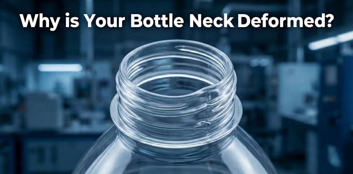
In the high-speed PET blow molding industry, neck deformation (Ovality) is a critical dimensional defect that directly compromises filling line efficiency and sealing integrity. When a client reports capping failures, gas leakage, or "jumping threads," the root cause is rarely the cavity design itself. It is almost always a failure in thermal management or mechanical alignment. In my 20 years of precision mold manufacturing in Zhongshan, I have verified that maintaining the dimensional stability of the neck finish requires strict control of process variables before the mold closes. I have seen factories lose entire shifts of production because they focused on blowing pressure instead of oven cooling. This guide details the technical execution of fixing neck ovality.
PET bottle neck deformation is a dimensional defect caused by exceeding the Glass Transition Temperature (Tg) of the neck finish or by mechanical shear forces during transfer. To eliminate ovality, operators must maintain neck temperature below 50°C via shield adjustment, ensure concentric alignment of the star wheel, and verify that mold neck holders are made of durable stainless steel to prevent wear.
1. Understanding "Neck Ovality": Why Heat Management is the Absolute Priority
Problem: The bottle body is blown correctly, but the thread diameter (T dimension) exceeds the tolerance of ±0.2mm, causing capping failures.
Agitation: Operators often incorrectly adjust the blowing pressure or cycle time, which fails to address the root cause. This leads to continued scrap production and potential complaints about leakage from filling lines.
Solution: The focus must be shifted to the thermal protection of the neck finish during the heating phase.
In two-stage stretch blow molding, the neck finish is fully crystallized and dimensionally set during the injection molding phase. During the blowing phase, our engineering objective is to maintain this original dimension. The physical properties of PET change drastically at the Glass Transition Temperature (approx. 70°C).
- Below Tg: The material remains in a rigid state.
- Above Tg: The material enters a viscoelastic state, becoming susceptible to deformation.
If the neck finish absorbs radiant heat and exceeds 60°C, the internal stress from the heating spindle (mandrel) or the mechanical clamping force of the transfer arm will permanently distort the geometry. Once the material cools, this deformation is locked in.
Therefore, the first rule of troubleshooting is thermal isolation. We must ensure that while the preform body reaches the optimal stretching temperature of 95°C-110°C, the neck finish remains strictly below 50°C.
I often tell my engineers: "The body must be soft, but the neck must be stone cold." If you touch the neck of a preform exiting the oven and it feels pliable, you are already producing scrap.
| Zone | Target Temp | Physical State | Tolerance Requirement |
|---|---|---|---|
| Neck Finish | < 50°C | Rigid / Stable | ± 0.15mm |
| Transition (Support Ring) | < 65°C | Semi-Rigid | ± 0.20mm |
| Body / Sidewall | 100°C - 110°C | Viscoelastic | High Stretch Ratio |
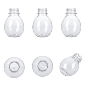
2. Step 1: Input Quality Control (IQC) – Preform Storage Deformation
Problem: The blowing parameters are optimized, yet the output bottles consistently show non-symmetrical ovality.
Agitation: Maintenance teams waste hours calibrating the machine, not realizing the input material is already defective.
Solution: Implement a strict preform inspection protocol to rule out "Creep Deformation" caused by improper storage.
Before any machine adjustment, we must verify the raw material. PET preforms are subject to "Cold Flow" or Creep if subjected to sustained compressive load.
- Stacking Load: In many warehouses, 40kg cartons are stacked 4-5 layers high. The hydrostatic pressure on the bottom layer preforms can mechanically compress the neck finish over time.
- Residual Heat: If preforms are packed immediately after injection without sufficient cooling, the residual heat softens the neck. The weight of the upper preforms causes the necks at the bottom to warp.
Inspection Protocol:
Do not load preforms blindly. Select 20 samples from the bottom of the pallet.
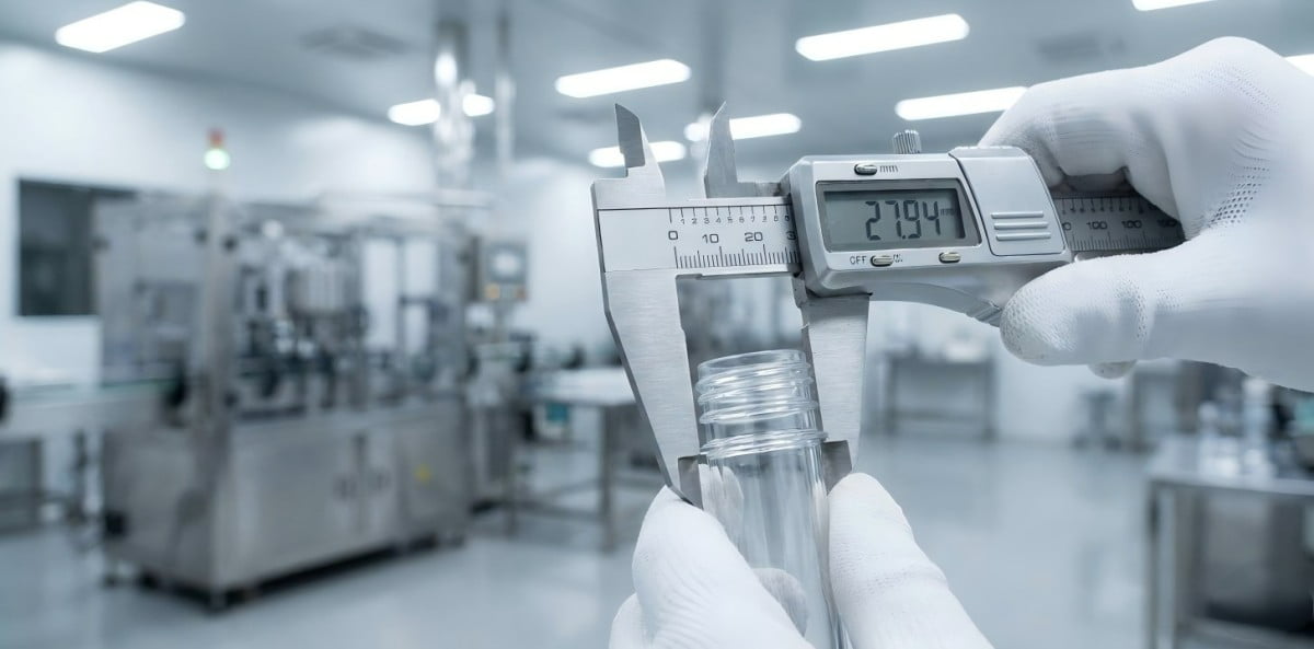
- Use a calibrated Vernier caliper.
- Measure the Inner Diameter (ID) and Outer Diameter (OD) at 0° and 90°.
- Rejection Criteria: If the ovality (difference between max and min diameter) exceeds 0.2mm before heating, these preforms are unsuitable for precision production.
We often see issues where the "Gate" is centered, but the neck is oval. This is a clear indicator of storage deformation, not machine misalignment. If you use deformed preforms, no amount of preform mold adjustment will fix the final bottle.
3. Step 2: Oven Thermal Profile – Optimization of Cooling Shields
Problem: The neck finish becomes soft to the touch immediately after exiting the heating tunnel.
Agitation: Increasing the ventilation airflow cools the preform body too much, resulting in "pearlescence" (cold stretching) without solving the neck heat issue.
Solution: Precisely adjust the mechanical cooling shields and ensure the water flow rate is sufficient to prevent radiant heat transfer.
In linear or rotary blowing machines, the "Cooling Shields" (protection plates) are the primary defense against ovality. These metal channels create a thermal barrier between the infrared lamps and the neck finish.
Critical Adjustments:
- Shield Height Definition: The shield must be positioned to cover the support ring by exactly 0.5mm - 1.0mm.
- If positioned too high, the lamp heat hits the support ring, causing the bottle to sit tilted in the mold.
- If positioned too low, infrared radiation directly strikes the thread root, causing immediate softening.
- Water Channel Efficiency: The shields are actively cooled by a chiller circuit.
- Target Water Temp: 10°C - 12°C.
- Flow Rate: Must be turbulent enough to remove heat instantly. If the return pipe feels warm (>20°C), the flow is restricted (often by scale or rust).
- Surface Check: The shield surface facing the lamps must be cold. If the shield itself becomes hot, it acts as a secondary radiator, heating the neck via conduction.
I advise installing a flow meter on the shield cooling circuit. A drop in water pressure is the leading cause of sudden neck ovality in summer months.
4. Step 3: Mandrel (Spindle) Interaction – Controlling Hoop Stress
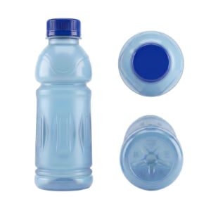
Problem: The neck deformation manifests as an expansion of the Inner Diameter (ID), causing loose fitment of the inner cap seal.
Agitation: The operator suspects the blowing pressure is too high, but reducing pressure causes poor bottle definition.
Solution: Inspect the heating mandrels for incorrect dimensioning or run-out (wobble).
The preform sits on a rotating spindle (mandrel) while traversing the oven. This interface is critical.
- Thermal Expansion: The coefficient of thermal expansion for PET is significant. As the preform heats up, the neck ID expands.
- Interference Fit: If the spindle head diameter is too close to the preform ID (e.g., zero clearance), the expanding plastic will bind against the rigid steel spindle. This creates "Hoop Stress," permanently stretching the neck.
Technical Requirement:
The spindle head diameter must be designed with a clearance of 0.15mm - 0.20mm relative to the preform nominal ID. This allows the preform to "float" slightly without stress.
Mechanical Run-out:
Check the chain drive system. If the spindle bearings are worn, the spindle will oscillate (wobble) during rotation. At high speeds, this centrifugal force applies cyclical side-loading to the warm neck, distorting it into an ellipse. Use a dial indicator to measure spindle run-out; it should not exceed 0.1mm.
5. Step 4: Transfer Star Wheel – Concentric Alignment
Problem: The bottle neck shows a distinct impact mark or "flat spot" on one side, or the support ring is bent.
Agitation: Adjusting the mold closing speed does not resolve the issue. The defect appears mechanical and repetitive.
Solution: Re-calibrate the synchronization between the transfer star wheel gripper and the mold center.
The transfer phase—moving the heated preform from the oven to the blow mold—is the moment of highest mechanical risk. The preform is in a semi-soft state. Any misalignment results in shear force.
Alignment Protocol:
The center of the star wheel gripper pitch circle must align perfectly with the center of the blow mold cavity.
- Misalignment Effect: If the alignment is off by even 0.5mm, the gripper forces the preform into the mold lock ring. The rigid steel mold acts against the soft plastic, crushing the side of the neck.
- Gripper Tension: We often find factory technicians increasing the spring tension on grippers to prevent dropped preforms. Do not do this. Excessive clamping force squeezes the warm neck finish. The gripper should hold the preform gently, supported by the support ring, not by radial compression.
Use a dedicated centering gauge (mandrel) during maintenance to align the transfer arm. Do not rely on visual estimation. Visual checks are not accurate enough for high-speed production.
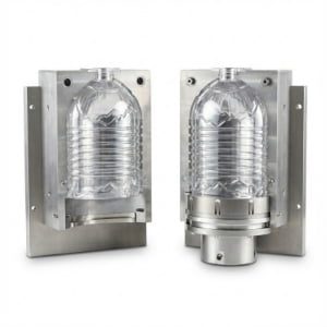
6. Step 5: Mold Neck Holders – Material Selection and Wear
Problem: A visible "step" or "clamping line" appears on the thread or locking ring, and the thread profile is distorted.
Agitation: The customer reports that the cap torque is inconsistent.
Solution: Inspect the Neck Holders (Neck Blocks) for wear, gap, or misalignment. Prioritize Stainless Steel over Aluminum for these components.
In the blow mold assembly, the Neck Holders are subjected to high mechanical stress. They must hold the preform against 35-40 bar of blowing pressure and endure millions of clamping cycles.
Material Analysis: 7075 Aluminum vs. S136 Stainless Steel
- 7075 Aluminum: While 7075 is an excellent, aviation-grade material often used for mold cavities due to its thermal conductivity, it is mechanically softer than steel. For neck holders, which experience repetitive high-pressure impact and friction, aluminum edges can wear down over time. This wear creates a gap at the parting line.
- S136 Stainless Steel: We recommend using S136 (or equivalent corrosion-resistant stainless steel) for neck holders. The inherent hardness and density of stainless steel provide superior resistance to compressive wear and parting line deformation compared to aluminum.
Gap Analysis:
If the parting line edges are worn, the high-pressure air will force the neck material to expand into the gap. This creates a ridge or an oval cross-section. Regular maintenance involves cleaning the mating surfaces to remove 0.03mm+ debris that can prevent full closure.
7. Step 6: Post-Mold Cooling – Stabilizing the Output
Problem: The bottle dimensions are correct inside the mold, but ovality is detected at the packing station.
Agitation: The defect seems random and unrelated to specific cavities.
Solution: Ensure the machine's integrated air cooling device is functioning and minimize mechanical impact during ejection.
Even after the blowing cycle is complete, the neck finish retains residual heat because it was not in direct contact with the chilled mold cavity walls (to protect thread geometry). The neck temp may still be 55°C upon ejection.
Air Cooling Device Implementation:
Most modern blowing machines are equipped with Air Cooling Nozzles or blowers at the outfeed track.
- Function: A directed stream of air must be targeted specifically at the neck finish as the bottle leaves the mold wheel. This airflow removes residual heat (hysteresis), quickly lowering the temperature to freeze the dimension.
- Verification: Operators should check if these nozzles are active and correctly aimed. Without this cooling, the neck remains pliable.
Impact Management:
- Drop Height: If the machine uses a gravity drop ejection, reduce the vertical distance to the conveyor.
- Slide Chutes: Ensure the slide chutes are lined with soft material (like UHMWPE) to prevent impact deformation on the warm neck.
8. Summary: Precision Engineering vs. Thermal Variables
Troubleshooting neck ovality requires a systematic engineering approach. We must isolate the thermal variables (oven) from the mechanical variables (mold and transfer).
The Vivian Factory Protocol:
- Verify Input: Reject preforms with >0.2mm static deformation.
- Isolate Heat: Shield water temp <12°C; Neck temp <50°C.
- Eliminate Stress: Spindle clearance >0.15mm; Gripper alignment <0.1mm concentricity.
- Lock the Mold: Use S136 Stainless Steel Neck Holders to ensure long-term wear resistance.
| Fault Indicator | Root Cause | Corrective Action |
|---|---|---|
| Material Softness | Excessive Radiant Heat | Increase shield water flow / Lower shield height |
| Asymmetric Flat Spot | Transfer Misalignment | Re-align Star Wheel using Centering Gauge |
| ID Expansion | Spindle Interference | Verify Spindle OD vs. Preform ID |
| Parting Line Offset | Worn Locking Edges | Replace Aluminum Inserts with S136 Stainless |
| Post-Mold Ovality | Residual Heat Deformation | Check Outfeed Air Cooling Nozzles |
For detailed consultation on your specific bottle design or to upgrade your tooling to stainless steel standards, please review our technical specifications. Our factory service team specializes in diagnosing these high-speed production variables.
FAQ: Technical Troubleshooting Queries
Q1: Can we compensate for neck ovality by increasing the mold cooling time?
No. The mold cooling circuit removes heat from the bottle body via the cavity walls. The neck finish is thermally isolated in the neck blocks. Increasing cycle time reduces OEE without effectively cooling the neck. The neck must be protected in the oven.
Q2: What is the correct clearance for the Neck Holder parting line?
The target is 0.00mm (Zero Gap) under clamping load. Any visible gap will result in material deformation due to the high blowing pressure (35-40 bar).
Q3: Why do we observe ovality only on specific cavities?
This indicates a localized failure. Check the specific oven spindle (mandrel) associated with that bottle for run-out. Also, check the cooling water channel for the neck shields in that specific section of the oven—blockages often occur in single loops.
Q4: Is S136 steel mandatory for neck holders?
For high-volume production, it is highly recommended. While 7075 Aluminum is a premium aviation material, it is softer than steel. Under repeated high-pressure clamping, aluminum edges can wear, leading to gap formation. S136 Stainless Steel offers superior durability and wear resistance for the neck locking area.
Q5: How does the support ring geometry affect ovality?
A weak or thin support ring will warp under oven heat. Since the support ring is the datum for the bottle's position in the mold, a warped ring leads to angular misalignment. This misalignment forces the neck against the mold walls during closing, causing distortion.
For advanced mold configurations or preform mold optimization, visit our technical center at petmolder.com.