I am Vivian. I have 20 years of experience in PET mold manufacturing and quality control in Zhongshan, China. You want to produce a 5L edible oil bottle. You need a reliable bottle design. Large containers with deep grips present a severe engineering challenge. The deep cavity forces extreme material stretch. Standard methods fail. Engineers must apply precise thermodynamic and mechanical solutions. We build advanced tooling. We use high-precision CNC machines. I will explain the exact engineering parameters you need to succeed.
Large PET bottles with handles require preferential heating and active mold inserts. The deep grip geometry forces extreme material stretch. Standard static molds cause web tearing and blowouts under 40 Bar pressure. You must control the biaxial orientation to maintain a minimum wall thickness of 0.15mm and prevent structural failure.
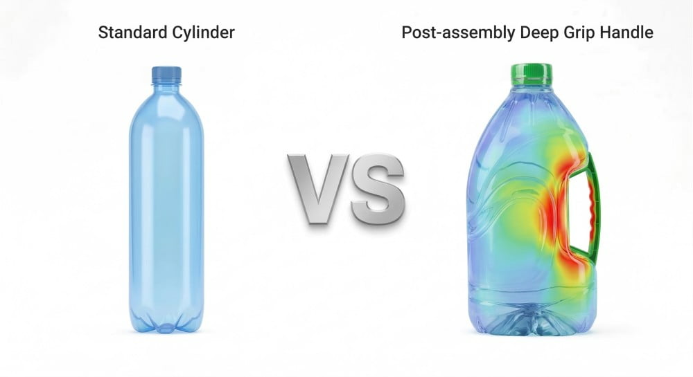
The Asymmetric Challenge: Defying natural biaxial orientation.
The deep grip creates an extreme asymmetric stretch ratio. The plastic thins out and reaches its yield limit. The bottle structure fails. We must control the material distribution to solve this physical problem.
The asymmetric challenge breaks natural biaxial orientation. PET expands into a uniform cylinder naturally. A deep grip forces the plastic into a narrow, asymmetrical cavity. High pressure pushes the material beyond its elasticity limit. This causes severe stress whitening. You must calculate the precise stretch ratio before cutting steel.
You must understand polymer physics. Please review standard engineering literature on Biaxial Orientation. We heat the plastic preform. The stretch rod pushes the plastic downward. High-pressure air pushes the plastic outward. The polymer chains align. The plastic gains immense mechanical strength. A standard round bottle expands evenly. The wall thickness remains uniform.
A large PET bottle with an integrated handle behaves differently. The deep grip destroys the structural symmetry. The mold features a massive inward cavity. The expanding plastic hits this metal cavity. The plastic must stretch much further into the deep corner. The localized stretch ratio climbs rapidly. The plastic reaches its yield limit. The molecular structure breaks down.
Do not ignore this physical law. This is a fatal mistake. Many engineers design complex bottles on computers. They send the 3D files to a factory. The factory cuts the PET blow mold. The factory tests the mold. The bottle fails completely. The plastic cannot stretch into the deep groove. The material turns white. We call this stress whitening. Stress whitening destroys the mechanical strength. The handle breaks during transport.
We analyze the geometry rigorously. We use simulation software. We measure the distance from the preform center to the deep grip root. We compare it to the main bottle diameter. We build strong molds to control this extreme process. We use 7075 aluminum for the main mold body. 7075 aluminum transfers heat extremely fast. We use S136 stainless steel for the neck ring and high-wear areas. Stop buying cheap steel molds. Cheap steel deforms under 40 Bar pressure. It ruins your dimensional tolerance.
Material Stretch Parameters
| Parameter | Standard Cylinder | Deep Grip Bottle | Result |
|---|---|---|---|
| Axial Stretch Ratio | 2.5 | 2.5 | Normal |
| Hoop Stretch Ratio | 4.0 | 6.5 | Extreme |
| Wall Thickness | 0.30mm | 0.05mm | Failure |
| Stress State | Even | Unbalanced | Whitening |
The Primary Failure Mode: Web tearing and localized blowouts.
Static molds create severe wall thinning at the handle root. The plastic drops below the critical thickness limit. High-pressure air escapes. We must implement dynamic mold technology to stop this immediate failure.
The primary failure mode is web tearing and localized blowouts. Static molds fail to distribute material into deep grips. The wall thickness drops below 0.15mm. The plastic tears. The 40 Bar air escapes violently. This pressure imbalance also causes poor mold closure and sharp parting line steps.
I inspect many standard production lines. I see static molds failing daily. A static mold has no moving internal parts. The two mold halves close. The machine injects the air. The plastic hits the mold wall. The deep grip requires a massive amount of plastic. The plastic must stretch far to fill the corner. The wall thickness drops rapidly. The absolute safe limit is 0.15mm. The wall often becomes 0.05mm. The plastic rips open. We call this web tearing.
The blowing machine uses 40 Bar of high pressure. 40 Bar is a massive force. The web tears. The 40 Bar air escapes through the hole instantly. We call this a blowout. The blowout makes a loud noise. Production stops. The operator must clean the machine. You lose production time. You waste expensive material. Do not use static molds for extreme deep grips. This is an amateur mistake.
The blowout causes a dangerous secondary problem. The pressure drops inside the cavity. The mold locking mechanism loses its internal balance. The two mold halves separate slightly. The plastic pushes into the small gap. The plastic forms a sharp parting line step. A sharp parting line step cuts the consumer's hand. Stop accepting sharp parting lines. You must use massive mold locks.
We solve this with heavy-duty mold design. We design aggressive cooling channels. We drill 10mm cooling water lines. We place the water lines exactly 15mm from the cavity wall. Do not place them 25mm away. Distant water lines cool the mold too slowly. The mold stays hot. The plastic sticks to the metal. The cycle time increases. Efficient cooling saves 2 seconds per cycle.
Defect Analysis Matrix
| Defect Name | Visual Symptom | Root Cause | Engineering Solution |
|---|---|---|---|
| Web Tearing | Hole at handle base | Extreme stretch thinning | Active mold inserts |
| Blowout | Loud noise, torn bottle | Wall thickness < 0.05mm | Preferential heating |
| Sharp Parting Line Step | Razor edge on seam | Pressure imbalance / weak lock | Strengthen mold locks |
| Stress Whitening | White cloudy plastic | Over-stretching cold PET | Optimize oven temp |
The Thermal Prerequisite: Implementing Preferential Heating (PH).
Standard ovens heat the plastic evenly. The plastic forms a round shape. The handle area gets cold and stiff. We implement preferential heating to direct hot, soft material into the deep grip.
Preferential heating SBM is the standard thermodynamic solution. You adjust the oven infrared lamps to heat the preform asymmetrically. The handle side absorbs more heat. Hot PET has lower viscosity. It stretches further and actively distributes more material mass into the deep grip cavity.
You must heat the plastic strategically. Standard blowing machines heat the preform evenly. The preform rotates constantly inside the oven. All sides receive the exact same infrared energy. The plastic expands into a perfect cylinder. This is terrible for handle bottles. You need a specific thermal profile.
You must use preferential heating (PH) technology. Preferential heating changes the temperature distribution. You use special oven configurations. You stop the continuous rotation. You rotate the preform to expose one specific side to the infrared lamps longer. The handle side reaches 105°C. The back side reaches 95°C. Do not heat both sides to 105°C. The entire preform will melt and collapse.
Understand the viscosity physics. Hot plastic is soft. Cold plastic is stiff. Viscosity measures this resistance to flow. Hot PET has lower viscosity. The stretch rod pulls the hot plastic easily. The high-pressure air pushes the hot plastic fast. The hot plastic moves deeply into the handle cavity. The colder plastic stays thick at the back of the bottle. You get excellent material distribution. The wall thickness stays above 0.15mm at the critical grip root.
We adjust the oven lamps precisely. The oven contains multiple heating zones from top to bottom. We control the power percentage of each specific lamp.
Oven Temperature Profile
| Heating Zone | Handle Side Temp (°C) | Back Side Temp (°C) | Material Status |
|---|---|---|---|
| Zone 1 (Neck) | 85 | 85 | Stiff (Protects thread) |
| Zone 2 (Shoulder) | 98 | 92 | Medium flow |
| Zone 3 (Deep Grip) | 105 | 95 | High flow |
| Zone 4 (Base) | 90 | 90 | Structural support |
You must monitor the factory ambient temperature. Factory temperatures fluctuate. Summer is hot. Winter is cold. You must adjust the oven settings accordingly. Stop using the exact same recipe all year. The preferential heating profile requires strict daily tuning. The operator must check the preform surface temperature with an infrared pyrometer.
Preform Registration: The mechanics of orientation lock.
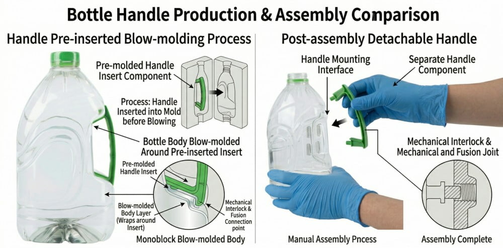
The oven heats the preform asymmetrically. The preform enters the mold randomly. The hot side misses the handle cavity entirely. We use a precise registration notch to lock the mechanical orientation.
Preform registration locks the mechanical orientation. The oven heats the preform asymmetrically. The preform must enter the mold with absolute precision. A mechanical registration notch sits under the support ring. The machine reads this notch and aligns the hottest side exactly with the handle cavity.
You use preferential heating successfully. One side of the preform is hot. One side is cold. The hot side must face the handle cavity perfectly. You need absolute alignment. You need a preform registration notch. The preform mold creates this small mechanical feature during injection. The notch sits directly under the support ring.
The blow molding machine uses a special sensor. It uses an optical camera or a physical mechanical pin. The preform exits the oven. The sensor locates the notch. The transfer arm grips the preform. The transfer arm rotates the preform to the exact mathematical angle. The arm places the preform into the open mold. The hot side points directly at the deep grip.
Do not skip the registration notch. Many factories try to save money. They buy standard cheap preforms without notches. This is a fatal engineering mistake. The orientation fails completely. The hot side faces the flat bottle wall. The cold side faces the deep grip. You get immediate web tearing. You get massive blowouts. You waste raw material.
Always design a 2.0mm deep notch. A shallow notch fails frequently. The sensor cannot read a 0.5mm notch accurately. We machine the neck ring carefully. We inspect the notch under a microscope. Check the notch dimensions every single day. A worn injection mold produces a bad notch. A bad notch ruins your entire blow molding process.
Machine synchronization is vital. The transfer arm must move fast. The preform loses heat rapidly in the open air. The arm moves the preform from the oven to the mold in 1.5 seconds. The arm rotates the preform during this rapid movement. High-precision servo motors provide the exact positioning.
Registration System Components
| Component | Function | Maintenance Requirement | Failure Result |
|---|---|---|---|
| Registration Notch | Physical reference point | Inspect for wear daily | Total loss of orientation |
| Optical Sensor | Reads the notch angle | Clean lens weekly | Misplaced hot side |
| Transfer Arm | Moves and rotates preform | Lubricate servo motors | Slow transfer / cold PET |
| Mold Cavity | Receives aligned preform | Check alignment pins | Asymmetric material flow |
Active Mold Inserts: Moving geometry for deep cavities.
Static molds rely purely on air pressure. The air stretches the plastic too thin in the corners. The handle base fails the drop test. We use active mold inserts to physically push the plastic.
Active mold inserts are the mechanical core for deep cavities. Heat alone is insufficient. Moving inserts retract during the pre-blow phase. They push inward during the main blow. Pneumatic cylinders drive them. They physically press the soft PET into the deep grip, preventing passive stretch thinning.
Heat does not solve extreme geometry. The deep grip geometry remains too severe. The stretch ratio is too high. You need direct mechanical intervention. You need active mold inserts. Standard molds are static and rigid. Static molds rely entirely on 40 Bar air pressure. The air pressure stretches the plastic too thin at the sharp corners. Active inserts move dynamically during the blowing process. They push the plastic mechanically.
The process happens in distinct stages. The machine starts the pre-blow process. The pressure is 10 Bar. The active inserts stay back in their retracted position. The plastic expands slowly. The machine starts the main blow process. The pressure spikes to 40 Bar. The pneumatic cylinders fire. The active inserts push inward at high speed. They physically press the hot plastic into the deep corner.
The plastic does not stretch passively. The plastic folds actively around the metal insert. The wall thickness remains robust. The minimum thickness stays safely above 0.15mm.
We use premium S136 stainless steel for the moving inserts. S136 resists wear perfectly. We harden the steel to HRC 52. Do not use aluminum for moving parts. Stop doing this immediately. Aluminum is too soft. The high-speed sliding motion creates friction. The friction creates metal dust. The dust ruins the moving mechanism. The insert jams. The machine crashes.
We design precision bronze guide rails. The inserts slide on these rails. The tolerance is 0.01mm. This extreme tolerance prevents plastic from entering the sliding gap. Plastic in the gap causes a sharp parting line step and halts production.
Moving Insert Specifications
| Part Name | Material | Hardness | Function |
|---|---|---|---|
| Mold Body | Alu 7075 | HRC 15 | Forms main bottle shape |
| Active Insert | S136 Steel | HRC 52 | Pushes deep grip |
| Guide Rail | Bronze alloy | N/A | Reduces sliding friction |
| Pneumatic Cylinder | Steel/Alu | N/A | Provides pushing force |
Synchronization: Timing the pneumatic actuation.
Improper timing destroys the bottle. Early movement hits cold plastic. Late movement tears solid plastic. We program the PLC to synchronize the pneumatic cylinders with exact millisecond precision.
Synchronization controls the pneumatic timing. The insert must move at the exact millisecond. Early movement hits unexpanded cold material, causing cold stretch marks. Late movement tears the cooled material at the web. Millisecond PLC synchronization is the core secret for advanced mold tuning.
Moving inserts demand perfect timing. The Programmable Logic Controller (PLC) controls this timing. The timing operates in milliseconds. You must tune the machine perfectly. The pressure blow curve dictates the exact movement window. The blow curve measures air pressure over time.
Do not trigger the insert early. Early movement is highly destructive. The plastic preform is still small. The pre-blow air just started. The insert moves inward prematurely. The metal insert hits the small plastic tube directly. The plastic is not fully heated at that contact point. The cold metal chills the plastic. The insert makes a deep mechanical mark. Engineers call this a cold stretch mark. The bottle looks ugly. The structural integrity fails.
Do not trigger the insert late. Late movement is equally destructive. The main blow air pushes the plastic against the outer mold wall. The plastic touches the cold metal mold. The plastic cools down instantly. The plastic solidifies. Then, the insert moves inward. The insert pushes against solid plastic. Solid plastic cannot stretch. The plastic breaks. You get instant web tearing.
You must trigger the insert exactly during the dynamic transition phase. The plastic is expanding rapidly. The plastic remains hot and highly flexible. The insert moves inward with the plastic flow. The mechanical speed must match the pneumatic expansion speed.
We use high-speed pneumatic valves. Standard valves are too slow and inconsistent. We buy premium valves from Germany or Japan. The valve response time is strictly 15 milliseconds. We monitor the pressure curve on the machine interface. We adjust the timer by 5-millisecond increments until perfect.
PLC Timing Chart
| Phase | Time (ms) | Air Pressure (Bar) | Insert Position | Resulting Action |
|---|---|---|---|---|
| Stretch Rod | 0 - 50 | 0 | Retracted | Axial orientation |
| Pre-Blow | 50 - 150 | 10 | Retracted | Initial expansion |
| Transition | 150 - 180 | 10 -> 40 | Moving Inward | Active material folding |
| Main Blow | 180 - 600 | 40 | Fully Extended | Final shape forming |
| Exhaust | 600 - 800 | 0 | Retracting | Pressure release |
Micro-Venting the Dead Space: Preventing trapped air in deep grips.
The deep grip traps air inside the cavity. The compressed air stops the PET from touching the metal. The plastic turns cloudy. We machine micro-vents to release the trapped air instantly.
Micro-venting the dead space prevents trapped air. The deep grip forms a blind aerodynamic corner. High-speed inserts trap air. The compressed air stops the PET from touching the mold. You must machine 0.05mm micro-vents. These vents maintain perfect aerodynamic balance and ensure sharp bottle details.
Air fills the empty mold cavity initially. The blowing machine starts. The plastic expands outward rapidly. The plastic pushes the air out of the mold. The air needs a clear escape route. The deep grip creates a severe aerodynamic problem. The deep grip is a dead space. It is a completely blind corner.
The active insert moves forward very fast. The plastic expands very fast. They trap the ambient air in the deep corner. The trapped air has nowhere to escape. The trapped air builds massive counter-pressure. The counter-pressure pushes back against the advancing plastic. The plastic stops expanding. The plastic never touches the cold metal mold wall.
This causes two major structural defects. First, the bottle surface becomes cloudy and dull. The plastic requires hard, direct contact with polished metal to become clear. Second, the handle shape is incomplete. The corners look rounded and soft. The end-user cannot install the external handle. The customer will reject the bottles.
You must release the trapped air. You must cut micro-vents into the mold steel. We use high-precision CNC grinding machines. We cut tiny grooves along the parting lines and directly around the active inserts. We cut the grooves exactly 0.05mm deep.
Do not cut 0.15mm grooves. This is a common manufacturing mistake. 40 Bar pressure is immense. The pressure pushes the hot plastic into a 0.15mm groove. The plastic forms sharp ridges on the bottle surface. The ridges cut fingers. 0.05mm is the perfect engineering dimension. 0.05mm lets the air out quickly. 0.05mm keeps the plastic safely inside the cavity.
Micro-Venting Specifications
| Location | Vent Depth | Vent Width | Purpose |
|---|---|---|---|
| Neck Ring | 0.03mm | 2.0mm | Release thread air |
| Main Parting Line | 0.04mm | 3.0mm | Release body air |
| Active Insert Gap | 0.05mm | Full perimeter | Prevent dead space trapping |
| Base Parting Line | 0.08mm | 5.0mm | Prevent base blowout |
We place the vents strategically. We surround the moving inserts with continuous vents. We place vents at the deepest corner radii. The aerodynamic balance becomes perfect. The plastic hits the mold wall instantly. The bottle comes out clear, sharp, and structurally sound.
Quality Validation: Wall thickness mapping via ultrasonic gauges.
Visual checks fail to detect hidden structural weaknesses. A beautiful bottle breaks during shipping. We map the wall thickness with ultrasonic gauges to guarantee absolute physical safety.
Quality validation requires strict wall thickness mapping. Visual checks are insufficient. You must use ultrasonic thickness gauges on the handle base. The industry standard for a 5L bottle requires a minimum thickness of 0.15mm to 0.20mm at the weakest point. This guarantees absolute safety during drop tests.
You finish the mold construction. You install the mold on the blow molding machine. You produce the first samples. You must test these samples rigorously. Visual inspection is never enough. A bottle looks beautiful on the outside. The internal wall thickness is a dangerous 0.05mm. You pack the bottle. You ship the bottle. The bottle falls. The bottle breaks instantly. You lose the customer forever.
You must use scientific measurement tools. We use high-end ultrasonic thickness gauges. We drop a small magnetic ball inside the bottle. The sensor probe touches the outside surface. The device maps the exact wall thickness precisely. We map the entire handle area. We check the top radius. We check the bottom root. We map 50 different data points.
We locate the weakest point. The weakest point is always the handle root. The minimum thickness here must be 0.15mm. 0.20mm is the optimal safe standard. If the thickness reads 0.10mm, we reject the bottle immediately. We return to the blowing machine. We adjust the preferential heating profile. We adjust the PLC timing. We fix the physical process.
You must perform physical drop tests. Fill the 5L bottle with water. Seal the cap tightly. Drop the bottle from a 1.5-meter height. Drop it flat. Drop it on the base. Drop it directly on the handle. The bottle must survive intact. The 0.15mm minimum thickness absorbs the shock energy. The proper biaxial orientation provides extreme elasticity.
Do not ship untested bottles. It is a fatal business mistake. The QC department must record all ultrasonic data. Save the data in the computer. Create a comprehensive quality report. Send the report to the buyer. This proves your professional engineering capability.
QC Testing Protocol
| Test Name | Equipment | Pass Standard | Frequency |
|---|---|---|---|
| Wall Thickness | Ultrasonic Gauge | Min 0.15mm at grip root | Every 2 hours |
| Drop Test | 1.5m platform | No rupture, no leaks | Once per shift |
| Top Load Test | Compression Machine | 30kg resistance | Daily |
| Visual Check | Light Box | Clear, no whitening | Every 30 mins |
5 Frequently Asked Questions (FAQ)
FAQ 1: Why does the plastic tear at the handle of a large PET bottle?
Answer: The plastic tears because of extreme stretch ratios. Engineers call this web tearing or blowout. The deep grip geometry demands too much material displacement. The plastic gets excessively thin. It breaks under 40 Bar high pressure. You fix this problem with preferential heating ovens and moving mold inserts.
FAQ 2: What is Preferential Heating (PH) in PET handle bottle manufacturing?
Answer: Preferential heating is an advanced thermodynamic process. Standard ovens heat preforms evenly. PH ovens heat one side of the preform more to create a strict temperature difference. The hotter side has lower viscosity. It stretches further into the deep grip cavity. It actively prevents web tearing.
FAQ 3: How do moving mold inserts work for PET bottles with handles?
Answer: Moving mold inserts are dynamic mechanical components inside the mold cavity. Pneumatic cylinders push them inward exactly during the transition to the main blow phase. They physically press the soft PET into the deep grip. They prevent passive stretch thinning. We machine them from durable S136 steel.
FAQ 4: Can trapped air cause defects in PET bottle handles?
Answer: Yes. Trapped air causes severe structural defects. The deep grip is an aerodynamic blind corner. Compressed air prevents the plastic from touching the cold metal. It causes cloudy surfaces and incomplete physical shapes. You must machine 0.05mm micro-vents to release this trapped air rapidly.
FAQ 5: How do I ensure my PET handle bottle passes the drop test?
Answer: You must use an ultrasonic thickness gauge. You map the wall thickness specifically at the handle root. The minimum thickness must exceed 0.15mm. The material distribution must be uniform. This provides the correct elasticity for impact resistance. You adjust the machine settings until you pass.
Deep Grip Technology Summary Matrix
| Technology Element | Purpose | Critical Parameter | Failure Consequence |
|---|---|---|---|
| Preferential Heating | Improve material flow | 105°C front / 95°C back | Web tearing, cold stretching |
| Registration Notch | Lock preform angle | 2.0mm depth minimum | Total orientation failure |
| Active Inserts | Push plastic actively | 15ms valve response time | Thin walls, blowouts |
| Micro-Venting | Release trapped air | 0.05mm groove depth | Cloudy plastic, dull corners |
| QC Mapping | Validate safety | 0.15mm minimum thickness | Drop test failure, leakage |