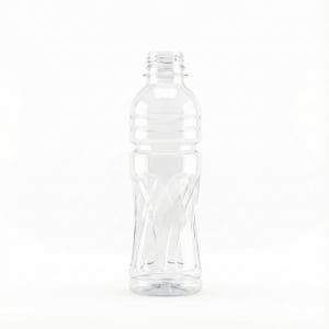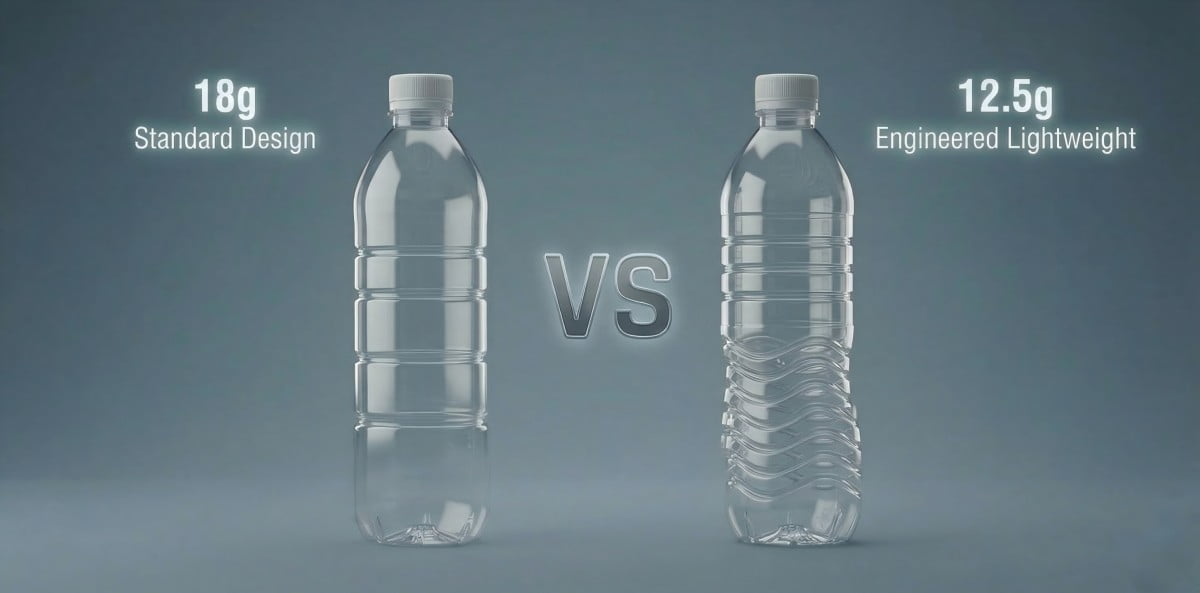
I am Vivian, the founder of PETmolder. I have 20 years of experience in PET mold manufacturing in Zhongshan, China. I manage factory quality control. Big brands reduce bottle weight by 2 to 3 grams today. Low-end brands reduce weight by 4 to 5 grams to win market share. I saw a client from Bangladesh recently. They wanted a 500ML water bottle. They used an 18-gram preform before. They wanted a 12.5-gram preform now. This removes 5.5 grams of plastic. This is a big change. We prioritize hardness first. We guarantee molding and pressure resistance. We consider aesthetics last. The new bottle design passed all physical tests. The client was happy. Today, my team and I share this process.
PET bottle lightweighting is a reverse engineering process to reduce plastic weight safely. Engineers measure the baseline top-load strength first. Then, we redesign the 3D bottle geometry, calculate the stretch ratio, and add structural ribs to increase hardness. We recommend this method to save material costs and prevent pallet collapse during transportation.
The Engineering Approach: Why planning prevents pallet collapse.
I heard from my client about a failed lightweighting project. Buying light preforms blindly often fails. Old molds do not distribute thin plastic properly. Pallets collapse in the warehouse. We suggest using reverse engineering to balance less material with structural mechanics.
To start lightweighting, avoid putting a light preform into an old mold. A proper engineering approach requires new 3D mold design. We advise balancing cost reduction with top-load strength. This careful planning prevents total pallet collapse when stacking heavy water bottles.
Many factory owners want to save money. They buy lighter preforms. They put them into old machines. The bottle walls become too thin. The bottom cracks. Top-load failure prevention fails. We do not recommend this practice.
A bottle is a physical structure made of Polyethylene terephthalate (PET). It carries axial load. The cap pushes down. The pallets stack high. If you remove plastic, you remove mass. Less mass means less structural strength. You need to replace the missing mass with smart geometry. This is the engineering approach.
We use a systematic method. We call it a 7-step guide. We do not guess. We measure data. We program CAD software based on math. A lightweight bottle should act like a heavy bottle under pressure.
The engineering approach changes the factory mindset. In the past, workers increased the blowing pressure to fix bad bottles. Now, engineers calculate the stretch ratio. We study the force vectors. We analyze the dimensional tolerance. If the math is bad, the bottle is usually bad.
Here is a comparison of the traditional approach and the engineering approach:
| Feature | Traditional Approach | Engineering Approach | Result |
|---|---|---|---|
| Preform Choice | Guessing by weight | Mathematical calculation | Good material distribution |
| Mold Cavity | Reuse old mold | Cut new steel from 3D design | Precise wall thickness |
| Testing | Squeezing by hand | Universal testing machine | Objective data validation |
| Pallet Safety | Low | High | Save money and prevent waste |
Avoid starting production without a clear plan. You waste time. You waste plastic. Engineering planning is highly recommended. The mold is the foundation. If the mold design is bad, the bottle is bad. We respect the physical properties of PET plastic.
Step 1: Baseline Data Collection - Establishing minimum top-load requirements.
In my workshop, we test every sample before we design. Guessing the required strength usually causes weak bottles. Production stops. We establish a minimum top-load requirement using a testing machine to guide the new design safely.
Baseline data collection sets the physical limit. We test the old bottle first. If the old 18g bottle holds 20 kgf, the new lightweight bottle should also hold 20 kgf. We rely on objective data as the primary standard for the new design. Do not guess the strength.
You cannot improve what you do not measure. Many buyers say, "Make it strong." "Strong" is not a number. "Strong" is a bad instruction. We need exact numbers. We measure the vertical top-load strength. We use kilograms-force (kgf) or Newtons.
If you have an 18-gram bottle, we put it in the machine. The machine pushes down. The bottle bends. The machine records 20 kgf. This 20 kgf is our baseline data. We write this number down.
Now, you want a 15-gram bottle. We remove 3 grams of plastic. The target for the 15-gram bottle is still 20 kgf. It needs to meet the baseline. If it only holds 15 kgf, the design is too weak. We need to redesign the 3D model.
Do not skip the baseline data collection. You will not know if your new bottle is good or bad.
We test different parts of the bottle.
- Top-load strength: This measures the downward pressure. It simulates stacking pallets.
- Radial rigidity: This measures the side pressure. It simulates a hand holding the bottle.
- Burst pressure: This measures internal force. It is used for carbonated drinks.
For water bottles, top-load strength is the most important metric. Pallets are heavy. The bottom layers carry the weight of the top layers. If one bottle fails, the whole pallet tilts.
| Test Parameter | Old Bottle (18g) | New Target Bottle (15g) | Pass/Fail Criteria |
|---|---|---|---|
| Top-load (kgf) | 20 kgf | 20 kgf | Aim to meet or exceed 20 kgf |
| Wall Thickness | 0.25 mm | 0.18 mm | Maintain uniform distribution |
| Empty Weight | 18 grams | 15 grams | Adhere to target weight |
We document all baseline data. This data goes to the CAD designers. The designers use this data to calculate the new geometry. Data prevents arguments. Data guides the mold quality.
Step 2: Preform Selection and Stretch Ratio Verification.
I saw a client waste plastic on bad preforms last year. Short preforms do not stretch well. The wall thickness becomes uneven. The bottle bursts. We calculate the axial stretch ratio and radial stretch ratio to ensure safe material distribution.
Preform selection dictates the final wall thickness. We calculate the axial load and stretch limits. The standard area stretch ratio should stay between 8 and 12. This helps the thin plastic reach its physical extension limit smoothly. Avoid using preforms with untested dimensions.
An injection mold dictates the starting mass of the plastic. When you reduce bottle weight, the preform changes. It becomes shorter. It becomes thinner. Stretching a short preform into a tall bottle is very difficult. The physics limit the stretch.
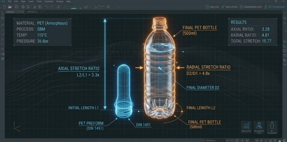
We calculate the stretch ratios carefully. There are two main ratios.
- Axial Stretch Ratio: This is the vertical stretch. It is the bottle length divided by the preform length under the neck.
- Radial Stretch Ratio: This is the horizontal stretch. It is the bottle diameter divided by the preform inside diameter.
We multiply the axial ratio by the radial ratio. This gives us the Area Stretch Ratio. The PET stretch ratio calculation is an important engineering step. The area stretch ratio usually performs best between 8 and 12.
If the ratio is below 8, the plastic does not stretch enough. The material does not align its molecules. The bottle is weak.
If the ratio is above 12, the plastic stretches too much. The wall becomes too thin. It breaks during blowing. Avoid buying preforms without calculating the ratio.
When we do PET preform weight reduction, we design the preform and the bottle together in the software.
| Preform Parameter | Stretch Ratio Impact | Result on Bottle |
|---|---|---|
| Core length | Affects Axial Ratio | Determines bottom thickness |
| Inside diameter | Affects Radial Ratio | Determines sidewall strength |
| Wall thickness | Affects overall mass | Determines total weight |
The stretch rod pushes the preform down. The air blows the plastic out. The material needs to reach the mold walls at the right time. If the preform is too thin, it cools too fast in the air. It does not reach the corners.
Always verify the stretch ratio before programming the CNC machines. Math saves steel. Math saves time.
Step 3: Modifying the Shoulder Profile for Optimal Load Transfer.
I heard from my client about crushed shoulders during transport. Flat shoulders trap stress easily. The thin plastic buckles under pressure. The bottle fails. We suggest increasing the shoulder angle to transfer the vertical load smoothly to the sidewall.
Modifying the shoulder profile optimizes load transfer. We advise against flat shoulders because they create stress concentration. We design steeper shoulders. A steep shoulder acts like an architectural structure. It moves the downward force from the cap directly to the strong cylindrical sidewall.
The bottle shoulder is a critical transfer point. Top-load pressure pushes down on the cap. The neck transfers this force to the shoulder. The shoulder must transfer this force to the sidewall.
If the shoulder is flat, the force stops. Stress concentration occurs at the flat corner. The plastic is thin here due to lightweighting. The flat shoulder buckles inward. The bottle collapses. We avoid this design.
We redesign the PET bottle shoulder design. We increase the angle. A steeper angle provides a direct path for the force. The force slides down the steep angle. It reaches the cylindrical sidewall. The sidewall is the strongest part of the bottle.
Think of building a roof. A flat roof holds heavy snow. The roof bends. A steep roof lets the snow slide off. The walls carry the weight. A bottle works the same way.
| Shoulder Type | Force Transfer | Stress Concentration | Expected Result |
|---|---|---|---|
| Flat Angle (Low) | Poor | High at the radius | High risk of buckling |
| Steep Angle (High) | Excellent | Low, evenly distributed | Better top-load strength |
We use CAD software to simulate the force. We change the shoulder angle degree by degree. We look for the optimal load transfer path.
Sometimes, marketing teams want flat shoulders. They say it looks modern. I tell them, "A flat shoulder requires thick plastic. You want a 15-gram bottle. A flat shoulder will likely fail." Engineering guides the design.
A steep shoulder also helps the blowing process. The plastic flows down the mold cavity easier. It does not get stuck at a sharp corner. The material distribution becomes more uniform. Uniform thickness means stable strength.
Step 4: Applying Structural Ribs to Compensate for Thinner Walls.
I saw a lightweight bottle bend easily in the hand. Thin walls lack radial rigidity. Consumers complain about the bad hand feel. We recommend adding structural ribs to the 3D bottle design to replace material mass with strong geometry.
Structural ribs improve the hand feel and hardness of lightweight bottles. When you remove 3 grams of plastic, the sidewall loses rigidity. We suggest adding horizontal stripes or wavy grooves to the 3D model. These geometric structures increase bending resistance without adding extra weight. Avoid leaving walls flat.
Plastic mass provides stiffness. When you remove mass, you lose stiffness. A 15-gram bottle has very thin walls. If the 3D design leaves the wall as a flat cylinder, it is weak. When a person holds the bottle, it squeezes inward. The water spills. The hand feel is bad.
We fix this with geometry during the CAD design phase. We design a structural ribs blow mold model. We add horizontal stripes to the bottle body. We add wavy grooves.
These ribs change the second moment of area (also known as the moment of inertia). This is a mechanical law. A corrugated steel sheet is stronger than a flat steel sheet. A ribbed plastic wall is stronger and harder than a flat plastic wall.
Avoid leaving the sidewalls perfectly flat on a lightweight bottle. The bottle will lack radial rigidity.
Once the 3D design is finalized with these ribs, the CNC machine simply reads the program and cuts the steel automatically. The engineering happens in the software, not during the cutting.
There are different types of structural ribs we design:
- Horizontal Ribs (Stripes): These wrap around the bottle. They provide excellent radial crush resistance. They stop the bottle from squeezing in the hand and give a better grip.
- Vertical Ribs: These run up and down. They add some top-load strength. They are less common on water bottles.
- Wavy or Geometric Ribs: These provide a mix of radial and top-load strength. They also look good and improve hardness.
| Rib Design | Primary Benefit | Application Location |
|---|---|---|
| Horizontal Stripes | Radial rigidity and good hand feel | Middle of the bottle |
| Wavy Grooves | Multi-directional hardness | Shoulder to base |
| Flat (No ribs) | Low rigidity | Not advised for lightweight |
We calculate the depth and width of the ribs carefully in the software. If a rib is designed too deep, the plastic cannot stretch into it smoothly. The plastic will thin out at the rib corner. We design shallow, smooth ribs. The plastic flows easily into smooth ribs, making the final product hard and comfortable to hold.
Step 5: Base Redesign - Adjusting Push-up Depth for Less Material.
In my workshop, we see deep bases cause rocker bottoms on light bottles. Light preforms cannot fill deep corners well. The bottle wobbles on the table. We adjust the push-up depth and corner radius to fit the reduced material volume.
Base redesign prevents rocker bottoms. Lightweight bottles have less PET material. We do not recommend using old deep base designs because the plastic will not fill the corners. We calculate a shallower push-up depth and a larger chamfer radius. A shallow base distributes the thin material evenly.
The base of a PET bottle is very complex. It has a push-up dome in the center. It has feet around the edge. It needs to stand flat on a table.
When you use an 18-gram preform, you have enough plastic to fill a deep base. The plastic pushes deep into the mold corners. The feet become thick and strong.
When you use a 15-gram preform, you have less plastic. If you use the old deep base mold, the plastic stops moving before it reaches the corners. The feet are not fully formed. The center push-up dome drops down. The bottle cannot stand flat. We call this a "rocker bottom."
Avoid using old base designs for new light preforms. You need to redesign the base.
We reduce the push-up depth. A shallower base requires less plastic to form. We increase the corner radius. A larger radius allows the plastic to flow smoothly into the feet.
| Base Component | Heavy Bottle Design | Lightweight Bottle Design |
|---|---|---|
| Push-up depth | Deep | Shallow |
| Corner radius | Small (Sharp) | Large (Smooth) |
| Material needed | High | Low |
The clearance at the bottom is critical. The gate is in the center of the base. The gate is the thickest part. If the gate drops below the feet, the bottle rocks. We design the push-up dome to lift the gate high above the table surface.
We also add small structural stripes to the base feet in the 3D model. These stripes prevent the thin plastic from warping during cooling. A flat, stable base is mandatory for the filling line. If bottles fall over on the conveyor belt, the factory stops. Base redesign improves stability.
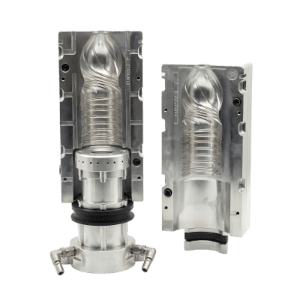
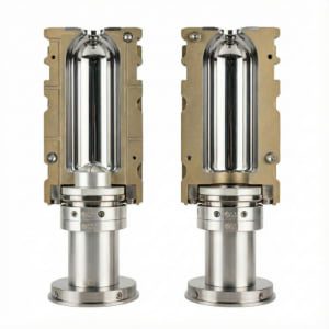
Step 6: CNC Tolerance and High-Efficiency Mold Cooling.
I saw poor cooling warp thin bottles. Thin walls cool very fast. Poor machining causes uneven walls. The defect rate rises. We use high-precision CNC tolerance and high-efficiency cooling channels to freeze the plastic instantly.
CNC tolerance and cooling channels control final dimensions. Thin walls need high-efficiency water channels. The material needs to freeze instantly. We recommend using S136 stainless steel or 7075 aluminum. Good machining ensures even thin walls. Avoid using cheap steel for lightweight molds.
A PET blow mold for a lightweight bottle requires strict thermodynamics. Thin plastic walls have very low thermal mass. They lose heat extremely fast.
When the hot plastic touches the mold wall, it needs to freeze instantly. If the mold is warm, the plastic shrinks. The bottle deforms. The top-load strength drops.
We design high-efficiency cooling channels. We drill water lines very close to the mold cavity. The water absorbs the heat from the aluminum or steel. Good cooling channels make the production cycle 2 seconds faster. This saves a lot of energy.
Avoid using cheap materials for the mold. We use 7075 aluminum or S136 stainless steel.
| Mold Material | Thermal Conductivity | Durability | Recommendation |
|---|---|---|---|
| 7075 Aluminum | Very High | Medium | Good for fast cooling, standard runs |
| S136 Stainless | Medium | Very High | Good for high volume, long life |
| Cheap Steel | Low | Low | Not recommended |
Dimensional tolerance is critical. We use 5-axis CNC machines. The tolerance should stay within 0.02 mm.
If the mold cavity has a dimensional error, the thin wall will have a thick side and a thin side. The thin side is a weak point. Under pressure, the bottle will bend at the thin side.
We polish the mold cavity to a mirror finish. A smooth surface helps the plastic flow fast. It also helps the air escape through the parting lines.
Good cooling speeds up the production cycle. A fast cycle saves money. It makes the factory profitable. High-precision CNC machining ensures every bottle matches the 3D design perfectly.
Step 7: Final Validation via Universal Testing Machine.
I heard from my client that physical tests save money. Visual checks hide invisible weak points. Unverified bottles fail during shipping. We test empty bottles with a universal testing machine to verify the top-load strength baseline.
Final validation requires destructive testing. A universal testing machine applies vertical pressure to the bottle. It records the peak force before the bottle buckles. The bottle should meet the Step 1 baseline. We advise against shipping bottles without physical testing.
The mold is finished. The bottles are blown. The project is not over. We verify the engineering design.
Visual inspection is not enough. A weak bottle looks exactly like a strong bottle. You cannot see top-load strength with your eyes. Do not rely only on visual checks.
We perform bottle top-load testing. We use a universal testing machine. This is a destructive test.
We place the empty, unsealed bottle on the steel plate. The machine lowers a flat metal disc onto the bottle neck. The machine pushes down slowly.
The machine records the force in real-time. The force curve goes up. Suddenly, the bottle wall buckles inward. The bottle collapses. The force curve drops. The highest point on the curve is the peak force.
If our Step 1 baseline data required 20 kgf, the new bottle needs to hit 20 kgf before it buckles.
| Test Stage | Action | Expected Result |
|---|---|---|
| Setup | Align bottle perfectly vertical | Zero misalignment |
| Compression | Apply downward pressure at 50mm/min | Resistance increases steadily |
| Yield Point | Wall buckles inward | Machine records peak force (kgf) |
| Validation | Compare peak force to baseline | Target $\ge$ 20 kgf |
If the bottle only hits 18 kgf, the design needs adjustment. We do not ship the mold. We go back to the CAD software. We check the wall thickness. We check the structural ribs. We adjust the 3D model and recut the steel.
Only a passing test validates the lightweighting project. We send the test report to the client. The data proves the safety. The client can load the pallets with confidence.
Complete Project Summary Table
| Step | Action | Engineering Goal | Practice to Avoid |
|---|---|---|---|
| Step 1 | Collect Baseline Data | Establish 20 kgf target | Guessing the bottle strength |
| Step 2 | Select Preform | Verify area stretch ratio (8-12) | Using untested short preforms |
| Step 3 | Modify Shoulder | Improve load transfer to sidewall | Keeping flat shoulders |
| Step 4 | Add Structural Ribs | Improve hand feel and hardness | Leaving 3D model walls flat |
| Step 5 | Redesign Base | Adjust push-up depth for low plastic | Using old deep base molds |
| Step 6 | CNC & Cooling | Ensure instant freeze and 0.02mm tolerance | Using cheap mold steel |
| Step 7 | Final Validation | Crush test with universal testing machine | Relying only on visual checks |
5 Frequently Asked Questions (FAQ)
FAQ 1: Where do I start when planning a PET bottle lightweighting project?
We suggest starting with baseline data collection. Do not change any designs first. Use a universal testing machine to measure the vertical top-load strength and radial rigidity of your current heavy bottle. Record the exact kilograms-force (kgf). This number becomes the mechanical baseline target for your new lightweight 3D design.
FAQ 2: Why do you advise against running a lighter preform in an old blow mold?
A lighter preform is physically smaller and thinner. If you blow it inside an old mold designed for a heavy preform, the axial and radial stretch ratios become unbalanced. The material stretches beyond its normal limits. The wall thickness becomes highly uneven. The bottle usually fails top-load tests and has a bad hand feel.
FAQ 3: How do structural ribs maintain bottle hardness with less plastic?
Structural ribs change the surface geometry of the 3D bottle model. This increases the cross-sectional moment of inertia. By adding horizontal stripes or wavy grooves, the thin plastic wall gains higher radial rigidity and bending resistance. The stripes improve the hand feel and provide the mechanical hardness that the missing plastic mass used to provide.
FAQ 4: What is the recommended shoulder angle for a lightweight bottle?
A lightweight bottle generally requires a steep shoulder angle. Flat shoulders create high stress concentration points at the radius. Thin plastic buckles there easily under downward pressure. A steep shoulder acts like a strong structural truss. It guides the vertical top-load pressure down smoothly and directly into the cylindrical sidewall.
FAQ 5: How is top-load strength verified before mass production?
We verify strength using a universal testing machine before the mold leaves the factory. This machine applies slow, progressive vertical pressure downward onto the empty bottle. It crushes the sample to find the yield point. We read the peak force data (kgf). This exact number proves if the structural design meets the baseline safety standard.