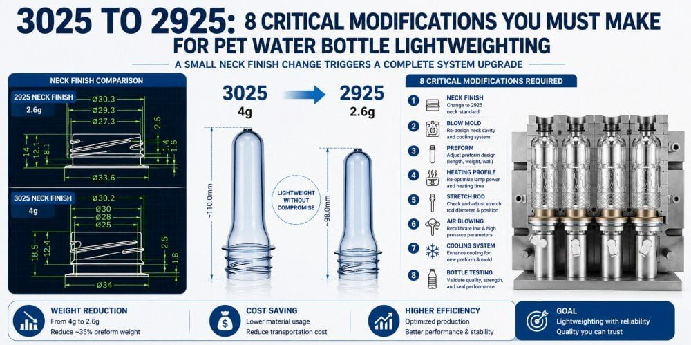
Converting from a 30/25 to a 29/25 neck finish offers significant resin savings for water bottling plants. However, executing this lightweighting transition requires precise mechanical retrofits to the blow molding machine—including gripper jaws, chute rails, and cooling shields—along with mandatory CNC remachining of the blow mold neck inserts and shoulder profiles.
Last week, an Indonesian beverage manufacturer operating a multi-volume water line (300ml, 500ml, 750ml, and 1500ml) contacted me regarding a comprehensive lightweighting project. Their entire production line currently utilizes standard 30/25 neck finishes. In an effort to reduce resin expenditure, their board approved a transition to the ultra-short 29/25 neck finish. However, the plant manager was highly concerned about the engineering risks: Would the existing blow molds be ruined? How extensive were the machine modifications? How long would the production halt last?
This scenario is increasingly common as global brands aggressively pursue PET lightweighting. The financial incentive is massive—shaving just 1.5 grams off the neck finish of a high-speed line can save hundreds of thousands of dollars annually in raw PET costs. But the execution is complex. Changing a neck finish is a systematic engineering overhaul, not a simple part swap. Today, my technical team and I provide a comprehensive breakdown of the eight essential hardware modifications required to safely and effectively convert a blowing line from 30/25 to 29/25.
1. The Financial Incentive: The "Million-Dollar" Logic Behind 29/25 Lightweighting
Transitioning from a 30/25 to a 29/25 neck finish maintains the internal diameter for filling but significantly reduces the thread height and support ring width. For a high-speed line producing 100,000 bottles daily, eliminating 1.5 grams of excess PET per preform generates massive annual resin savings.
Before analyzing the mechanical retrofits, it is vital to understand the commercial driver behind this conversion. The 30/25 neck finish has been a reliable industry standard for decades, providing robust sealing for non-carbonated water. However, it contains structural redundancy. The threads are taller than necessary for a basic flat cap, and the support ring is thick and wide.
The 29/25 standard (often referred to as the ultra-short neck) was engineered specifically for ecological and economical efficiency. It retains a similar inner diameter (approximately 21.5mm), meaning the filling nozzle on the downstream equipment does not necessarily need a complete overhaul. The resin savings are derived entirely from the external geometry: shorter threads and a narrower, lighter support ring.
For a factory operating a rotary blowing machine producing 24,000 bottles per hour on a 20-hour shift, saving 1.5 grams per preform equates to saving 720 kilograms of pure PET resin every single day. Over a standard operational year, the raw material cost savings often cover the entire capital expenditure of the machine retrofitting within the first 6 to 8 months. However, capturing this profit requires navigating strict mechanical tolerances. If the retrofitting is not executed precisely, the savings will be instantly negated by high scrap rates and constant machine jamming. For further insights on optimizing material usage, refer to our 7-step engineering guide to reducing weight safely.
2. Mold Foundation Overhaul: The Inevitable Replacement of the Neck Insert
The first critical mold modification is replacing the neck insert. Because the 29/25 support ring is narrower and the neck is shorter, utilizing the original 30/25 mold causes the preform to slip downward during clamping, resulting in catastrophic blow-outs. Precise CNC-machined replacement neck rings are mandatory.
The physical interface between the unheated preform neck and the heated stretchable body is located at the mold’s neck support ring (neck insert). In a blow mold, this hardened steel or aluminum insert locks tightly beneath the preform’s support ring, suspending it securely while 35 bar of high-pressure air forces the soft polymer outward.
The 29/25 preform features a significantly smaller outer diameter on its support ring and a reduced overall neck height. If you attempt to run a 29/25 preform inside an unmodified 30/25 mold, the neck insert will not engage. The preform will simply drop down into the cavity. When the high-pressure blowing air is introduced, the unsecured preform will instantly rupture (blow out), sending molten PET and compressed air through the parting line.
To execute this transition safely, the tooling manufacturer must CNC-machine a completely new set of neck inserts. These new inserts must be milled to the exact micrometer tolerances of the 29/25 support ring to ensure an airtight pneumatic seal during clamping.
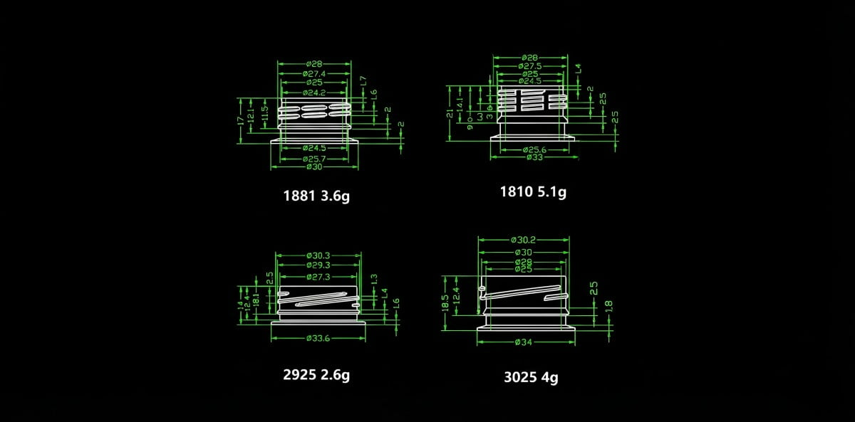
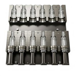
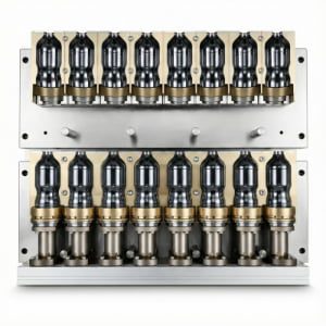
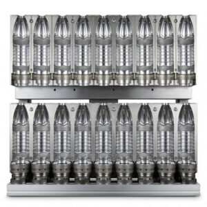
Visualizing neck finish variations. While this illustrates cosmetic neck differences, the engineering principle applies: transitioning from 30/25 to 29/25 requires completely new mold neck inserts to match the reduced support ring diameter.
3. Advanced Mold Evaluation: Shoulder Remachining and Argon Arc Welding
When shortening the neck finish, the original bottle shoulder contour often appears disjointed and physically stepped. Professional tooling facilities can utilize argon arc welding to fill the upper mold cavity and CNC-remachine a smooth, continuous shoulder transition, saving the cost of manufacturing entirely new molds.
Replacing the neck insert solves the clamping issue, but it exposes a secondary, aesthetic, and structural flaw: the shoulder transition. Because the 29/25 neck is significantly shorter than the 30/25, the existing shoulder curve of the mold will no longer align smoothly with the base of the new preform neck. The physical result is an abrupt, stepped ledge at the top of the bottle. This not only looks visually unappealing but also creates a sharp stress concentration point where the extremely thin PET can easily tear under vertical top-load.
Many factory owners assume they must discard their entire mold inventory and purchase completely new molds. This is an incorrect and expensive assumption. A highly capable tooling facility can evaluate the structural margins of your existing aluminum or stainless steel molds to execute a localized repair.
The engineering solution involves precise argon arc welding. Our technicians weld high-grade filler material of the same alloy (e.g., Al 7075 or S136) into the upper shoulder region of the mold cavity. The mold is then secured on a 5-axis CNC machining center. We program a new toolpath that smoothly blends the shortened 29/25 neck insert down into the existing main body of the bottle. This remachining restores the continuous curvature of the shoulder, eliminating stress risers while salvaging the bulk of the original tooling investment. To understand the intricacies of mold material modifications, consult Why Are Most PET Blow Molds Made of Aluminum? 4 Engineering Reasons Explained.
Table 1: Mold Modification Cost-Benefit Analysis
| Modification Strategy | Cost Impact | Execution Time | Structural Integrity Outcome |
|---|---|---|---|
| Complete New Mold Manufacturing | Highest | 15 – 25 Days | Perfect structural alignment and guaranteed lifespan. |
| Neck Insert Swap + Shoulder Welding | Moderate | 7 – 12 Days | Excellent; restores smooth transitions and eliminates stress points. |
| Neck Insert Swap Only (No Welding) | Lowest | 2 – 4 Days | Poor; creates visual steps, weak top-load resistance, and potential tearing. |
4. Preform Infeed Lifeline: Narrowing the Chute and Guide Rails
A smaller support ring requires tightening the tolerances of the preform unscrambler chute and guide rails. If the gaps are not recalibrated for the 29/25 dimensions, the preforms will fall through the rails or jam during gravity-fed delivery to the heating oven.
Moving away from the mold, we must address the machine’s mechanical handling systems. The journey of a preform begins in the hopper, moving up the elevator, and into the unscrambler. The unscrambler aligns the preforms and sends them sliding down a gravity-fed chute (guide rail) toward the infrared oven.
These guide rails function by suspending the preform solely by its support ring. Since the 29/25 preform support ring is visibly narrower in diameter than the 30/25, the gap between the two parallel rails of the chute is suddenly too wide. If left unadjusted, the 29/25 preforms will simply fall straight through the gap onto the floor. Even if they manage to hang, the excessive clearance will cause them to tilt, swing, and ultimately jam at the entry point of the star wheel.
The retrofit requires the maintenance team to physically loosen the guide rails and utilize precision caliper blocks to narrow the chute gap. If the original rails lack sufficient adjustment slots, new, dedicated 29/25 rail plates must be machined and installed. Consistent, jam-free preform feeding is the foundation of high-speed blowing.
5. Transfer Hub: Comprehensive Replacement of Gripper Jaws
Mechanical transfer arms and star-wheel grippers operate by clasping the preform beneath the support ring. The reduced neck diameter of the 29/25 standard necessitates installing a completely new set of dedicated gripper jaws to prevent slippage and high-speed preform ejection.
Inside the blowing machine, preforms are transferred from the oven to the mold cavity via high-speed mechanical transfer arms (star wheels). These arms utilize spring-loaded or cam-actuated gripper jaws.
The inner curvature and grip radius of a 30/25 jaw are machined specifically for that larger neck diameter. Attempting to use a 30/25 gripper on a 29/25 preform results in a loose, unsecured hold. During the violent acceleration and deceleration of the transfer cycle, the centrifugal force will violently eject the loose preforms out of the grippers.
There is no "adjustment" for this; it is a mandatory hardware replacement. Factory owners must procure a complete "neck conversion kit" from the machine manufacturer or a specialized parts supplier. This kit includes a full set of dedicated 29/25 gripper jaws. Upon installation, engineers must meticulously recalibrate the mechanical center point of transfer, ensuring the jaws align perfectly with the mold cavity center. Failure to align the grippers precisely will cause the preform to enter the mold at an angle, leading to severe thread crushing upon clamping. For troubleshooting thread damage, refer to Caps Won’t Seal? A 6-Step Protocol to Fix PET Bottle Neck Deformation.
6. Oven Micro-Management: Adjusting Mandrels and Cooling Shields
While heating mandrels often remain unchanged due to similar inner diameters, the oven’s water-cooling shields must be lowered. Lowering the shields protects the shorter 29/25 threads from direct infrared radiation, preventing severe crystallization and thread deformation.
The infrared heating oven is where thermodynamic precision dictates bottle quality. In a linear blowing machine, preforms are loaded onto rotating steel mandrels (plugs) that insert into the inner diameter of the neck.
- The Advantage: Because the 30/25 and 29/25 preforms share a very similar inner diameter (roughly 21.5mm), the existing heating mandrels frequently do not require replacement. A simple change of the high-temperature silicone O-rings on the mandrels (using a slightly thicker gauge) is usually sufficient to secure the 29/25 preform tightly during rotation.
- The Critical Modification: The height of the neck. To prevent the threaded neck from absorbing heat and deforming, the oven utilizes aluminum water-cooling shields that run parallel to the lamps, covering the threads. Because the 29/25 neck is shorter, the preform sits lower on the mandrel. If the cooling shield is not physically lowered to match, the top row of infrared lamps will blast direct heat onto the support ring and threads.
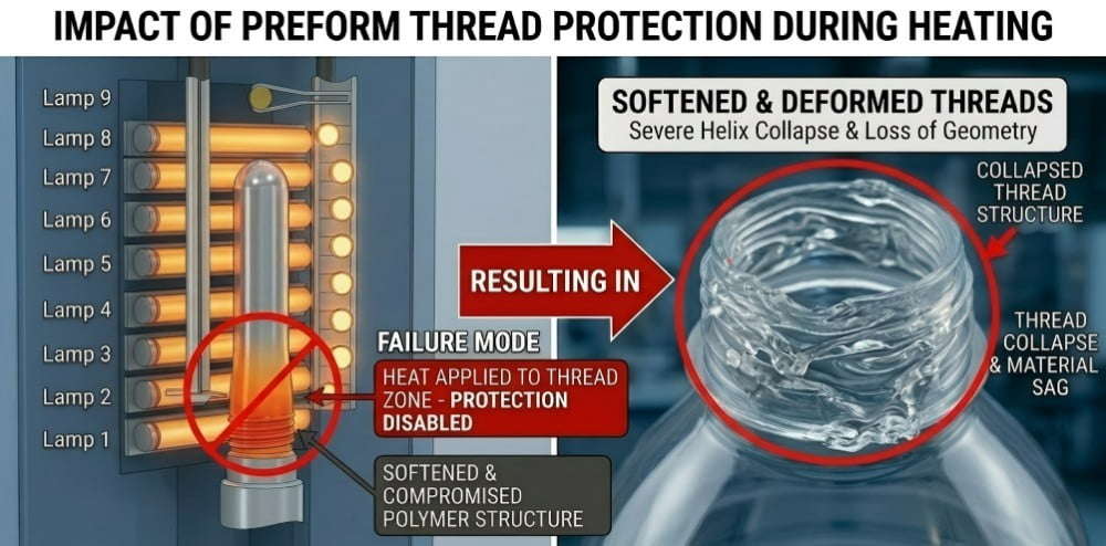
Failing to lower the oven cooling shields during a 29/25 conversion will expose the shorter threads to intense infrared heat, causing crystallization and catastrophic thread deformation.
The result is catastrophic crystallization (whitening) and thread shrinkage, making it impossible for the downstream capping machine to secure the closure. The engineering team must unbolt the cooling shield tracks and lower them by precise millimeters to ensure only the stretchable body of the preform is exposed to the thermal radiation. For a deep dive into resolving thermal defects on the neck, see Whitening on the Shoulder of PET Bottles: A 6-Step Guide to Repairing Localized Whitening.
7. Blowing Station Calibration: Nozzle Seals and Stretch Rod Zeroing
A shorter neck shifts the internal blowing position downward by 2-3mm. The high-pressure blowing nozzle stroke must be extended downward to ensure airtight sealing, and the stretch rod absolute zero point must be recalibrated to prevent catastrophic impact with the mold base.
Once the heated preform is clamped inside the new 29/25 neck insert, the actual blowing process commences. This requires high-pressure air (up to 40 bar) and mechanical stretching.
Because the 29/25 neck insert holds the preform 2 to 3 millimeters lower inside the mold block compared to the old 30/25 setup, the blowing nozzle—which descends from the top of the machine to seal against the preform opening—must travel further. If the nozzle stroke is not mechanically compensated downward, the rubber sealing gasket will not compress adequately against the top of the preform. When the 40-bar valve opens, high-pressure air will violently leak out of the top of the mold, resulting in a severe pressure drop and incompletely formed bottles.
Simultaneously, the stretch rod calibration is critical. The stretch rod pushes the preform axially to the bottom of the mold. Because the preform is now starting its journey 2-3mm lower, if the stretch rod stroke remains unchanged, it will over-extend. It will slam into the S136 stainless steel bottom mold insert, crushing the preform gate and potentially bending the pneumatic cylinder. The technician must reset the absolute zero point of the stretch rod to stop exactly 1.5mm above the new bottom mold surface. For detailed analysis on stretch rod alignment, consult Bottom Gate Off-Center? A 6-Step Protocol to Fix PET Bottle Eccentricity.
8. Closing the Line Loop: Downstream Capping System Upgrades
Lightweighting does not stop at the blowing machine. The 29/25 closure utilizes a distinct thread pitch and outer diameter. Successful conversion demands replacing the star wheels on the filling block and installing dedicated 29/25 capping chucks to finalize the package.
A common and highly disruptive oversight is focusing entirely on the blow molding machine while neglecting the downstream filling and capping equipment. The newly blown 29/25 bottles will exit the blowing machine flawlessly, only to jam violently at the filler.
The 29/25 neck is fundamentally different in pitch, thread count, and outer diameter from the 30/25. Therefore, the closure (the plastic cap) is entirely different.
- Cap Sorter and Chute: The hopper and chute that feed the caps down to the capper must be narrowed to handle the smaller 29/25 caps without flipping or jamming them.
- Handling Star Wheels: The star wheels that grip the bottle neck under the support ring through the rinsing and filling stations must be swapped for smaller 29/25 profiles.
- Capping Chucks: The most critical component is the capping chuck (the magnetic or servo-driven head that screws the cap onto the bottle). A 30/25 chuck will simply spin uselessly over a 29/25 cap. You must procure a full set of dedicated 29/25 capping chucks and recalibrate the application torque parameters.
Table 2: 30/25 to 29/25 Complete Retrofit Checklist
| Production Zone | Component to Modify | Required Action | Critical Engineering Goal |
|---|---|---|---|
| Blow Mold | Neck Inserts & Shoulder | Replace inserts; TIG weld and CNC remachine shoulder. | Ensure secure clamping and eliminate top-load stress risers. |
| Preform Infeed | Chute & Guide Rails | Narrow spacing via adjustment or replacement plates. | Prevent preforms from falling through or jamming before oven. |
| Transfer System | Gripper Jaws (Star Wheels) | Full replacement with 29/25 dedicated jaw sets. | Prevent preform ejection during high-speed centrifugal transfer. |
| Heating Oven | Water Cooling Shields | Lower shield height mechanically. | Protect shorter threads from infrared crystallization. |
| Blowing Station | Blowing Nozzle & Stretch Rod | Extend nozzle stroke downward; recalibrate rod zero point. | Guarantee airtight pneumatic seal; prevent mold base impact. |
| Capping System | Capping Chucks & Star Wheels | Full replacement of chucks and handling guides. | Ensure accurate torque application and prevent downstream crushing. |
Frequently Asked Questions (FAQs)
Q1: Is the success rate high for argon arc welding and remachining the mold shoulder? Will it affect mold longevity?
Yes, the success rate is exceptionally high provided the mold is constructed from premium aviation aluminum (e.g., Al 7075) or S136 stainless steel, and the welding is executed by specialized mold technicians using identical filler alloys. Post-weld CNC milling and polishing restore the surface finish completely without compromising the mold’s operational lifespan, though the tooling facility must evaluate the existing wall thickness to ensure sufficient material for the repair.
Q2: How long does the machine downtime last when retrofitting from 30/25 to 29/25?
If a comprehensive "conversion kit" (including new neck inserts, gripper jaws, chute guides, and capping chucks) is procured and staged in advance, an experienced engineering team can typically complete the hardware swap, mechanical recalibration, and thermal parameter adjustments within 2 to 3 working days.
Q3: Will the internal capacity of the bottle change after swapping to the 29/25 neck finish?
Yes, a minor volumetric reduction occurs. Because the neck finish is physically shorter, the overall height of the container decreases, slightly reducing the brimful capacity (by a few milliliters). If exact fill-level precision is mandatory, the tooling engineers can perform minor volumetric compensation by slightly expanding the shoulder cavity during the remachining phase.
Q4: Why do my heating mandrels feel loose after switching to the 29/25 preform?
While the theoretical inner diameter for both 30/25 and 29/25 is roughly 21.5mm, actual manufacturing tolerances vary between preform injection suppliers. If the mandrel feels loose, causing the preform to tilt in the oven, you do not need new steel mandrels. You can execute a low-cost fix by replacing the high-temperature silicone O-rings on the mandrels with O-rings of a slightly thicker cross-section to secure the grip.
Q5: Is the 29/25 lightweighting conversion suitable for all types of beverages?
No. The ultra-short 29/25 neck finish is engineered specifically for non-pressurized liquids like still pure water and mineral water. It lacks the deep thread engagement and robust support ring required to handle the immense internal gas expansion pressure generated by Carbonated Soft Drinks (CSD). CSD applications strictly require standard profiles like PCO 1881 or 1810 to prevent catastrophic cap blow-off.
Summary: Cost & Feasibility of 30/25 to 29/25 Conversion
| Retrofit Metric | Assessment / Detail | Engineering Recommendation |
|---|---|---|
| Primary Incentive | 1.0g – 1.5g PET resin saved per bottle. | Highly profitable for high-volume still water lines. |
| Blow Mold Retrofit | Neck insert replacement + Shoulder remachining. | Mandatory to prevent blow-outs and structural stress points. |
| Machine Parts Required | Gripper jaws, cooling shields, nozzle seals. | Must utilize manufacturer-specific conversion kits; no DIY workarounds. |
| Estimated Downtime | 2 to 3 working days (with prepared parts). | Schedule during off-peak maintenance windows. |
| Downstream Impact | Requires new capping chucks and star wheels. | Evaluate full-line compatibility before altering the blowing machine. |
Related Technical Guides:
- From Concept to Production: What Are the 8 Steps to Custom PET Bottle Molds?
- The Ultimate Guide to Preform Neck Finishes: How to Choose the Right Standard for Your Bottle
- PET Bottle Lightweighting: A 7-Step Engineering Guide to Reducing Weight Safely
- Caps Won’t Seal? A 6-Step Protocol to Fix PET Bottle Neck Deformation & Ovality
- Custom Blow Molds: 4 Reasons Your New Mold Won’t Fit Your Blowing Machine