Discover the engineering requirements for custom CSD bottle molds. Learn how to specify petaloid bases, preform weights, and cooling channels to ensure structural integrity and high-speed filling compatibility.
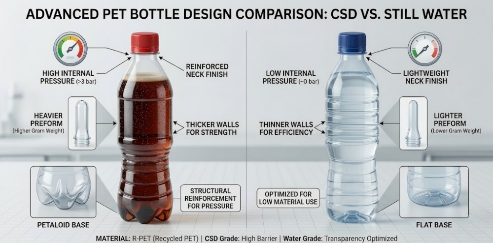
Converting a standard flat-bottom water bottle into a Carbonated Soft Drink (CSD) container requires a complete structural redesign, not just a base modification. CSD bottles demand specific hoop ribs, heavier preform masses, conformal cooling channels, and top-load resistance to withstand internal CO2 expansion and counter-pressure filling lines.
In my 20 years of managing overseas markets and factory operations for PET preform and blow mold manufacturing in Guangdong, China, I frequently consult with clients looking to expand their beverage portfolios. A recurring inquiry involves transitioning from still water production to carbonated beverages like sparkling water or soda. However, an engineering discrepancy often arises: buyers attempt to apply still water packaging principles to carbonated containers.
The physical demands of carbonated packaging are distinct. Internal gas pressure alters the fundamental stress distribution across the polymer. Today, my engineering team and I will objectively analyze the technical parameters of CSD tooling and detail five specific structural and material oversights that buyers should avoid during the procurement phase.
1. What is a Custom CSD Bottle Mold?
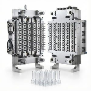
A custom CSD bottle mold is a highly pressurized tooling cavity engineered to form PET containers capable of retaining dissolved carbon dioxide. It utilizes specific geometries, such as petaloid bases and structural ribs, to prevent polymer creep and dimensional deviation under continuous internal pressure.
In our workshop, we treat CSD mold engineering as a thermodynamic and structural challenge. Unlike still water molds, which primarily manage vertical static loads (pallet stacking), a CSD mold must produce a container that resists continuous radial outward force.
When a beverage is carbonated, it is typically infused with 3.0 to 4.5 volumes of CO2. Once capped, this gas exerts consistent pressure against the internal walls of the PET bottle. According to packaging guidelines established by major equipment manufacturers like SIDEL and Krones, if the mold design does not account for this internal pressure, the polymer will undergo creep—a time-dependent mechanical deformation under constant stress.
To counteract this, a custom CSD bottle mold is CNC-machined with highly specific compensation geometries. The most critical is the petaloid base. This multi-footed bottom design (typically featuring 5 or 6 petals) is engineered to distribute the internal pressure evenly across a series of arches, preventing the base from reversing or rolling out. The mold must also be designed with precise parting line alignment and strict dimensional tolerances to ensure no pressure escapes during the high-pressure blowing phase, which often exceeds 30 bar. For a foundational understanding of how these molds operate within the factory, review What is PET Two-Stage Molding? The Ultimate Beginner’s Guide to the Factory Process.
2. How to Design a CSD Mold: Avoiding the Petaloid Conversion Oversight
Applying a petaloid base to a flat-walled still water bottle design will result in severe radial deformation. Internal CO2 pressure requires the integration of horizontal structural ribs and optimized shoulder curvatures to constrain the outward expansion of the PET material.
A frequent scenario involves an overseas client presenting an aesthetically pleasing, flat-panel juice or mineral water bottle design, requesting that we simply machine a petaloid base onto the bottom to make it suitable for soda. From an engineering perspective, this is an inadvisable practice.
When you pressurize a container, the stress is governed by physics. The hoop stress (the force exerted circumferentially around the cylinder) can be approximated by the formula:
$$ \sigma = \frac{P \cdot r}{t} $$
Where $P$ is internal pressure, $r$ is the internal radius, and $t$ is the wall thickness.
Because still water bottles are not designed to handle internal pressure ($P$), they often feature large, flat, label-friendly panels. If you introduce CO2 into a flat-walled design, the pressure will follow the path of least resistance. While the engineered petaloid base may remain stable, the flat side walls will bow outward, resulting in spherical or cylindrical expansion. This deformation renders wrap-around labels un-scannable and disrupts packaging logistics.
Before approving a mold design, you must require a rigorous 3D pressure simulation from your tooling supplier. A viable CSD mold design must incorporate specific horizontal structural ribs (often called hoop rings) along the body and a convex shoulder curve. These geometric features physically constrain the outward radial expansion. You can explore how base and body geometries interact in our PET Blow Mold Design Guide.
3. Cost of CSD Molds: Preform Weight and Stretch Ratio Incompatibility
Specifying a lightweight water preform for a CSD mold leads to material starvation in the petaloid base. The complex valleys of a 5-petal design require a higher polymer mass to ensure adequate wall thickness; failing to match the preform weight results in base rupture.
A critical variable in the cost and functionality of a CSD mold is the preform specification. The stretch ratio—the degree to which the PET polymer is expanded axially and radially—dictates the final mechanical strength of the bottle.
The petaloid base of a CSD mold features deep valleys and extended feet. Forming this complex geometry requires a substantial volume of PET material. A common procurement oversight is attempting to utilize a lightweight still water preform to minimize raw material expenditures. For instance, while a 500ml still water bottle can often be formed using a 15g preform, utilizing that same 15g preform for a 500ml CSD mold will lead to structural failure.
During the blowing process, the high-pressure air forces the limited polymer into the deep base crevices. This results in "material starvation." The wall thickness at the petal valleys will fall below the required dimensional tolerance, creating stress concentration points that will rupture upon carbonation. Prior to finalizing the mold drawings, you must confirm that the selected preform possesses sufficient mass. If you are unsure of how to evaluate preform parameters, consult our guide on How to Choose the Right Cavity Number for Your PET Preform Mold to align your upstream supply.
Table 1: Preform Mass and Application Parameters (500ml Volume)
| Application Type | Typical Preform Weight | Base Geometry | Wall Thickness Requirement |
|---|---|---|---|
| Ultra-Lightweight Water | 12g – 15g | Flat / Slight Push-up | Low |
| Standard CSD / Soda | 21g – 24g | 5-Petal Petaloid | High (Thick valleys required) |
| High-Carbonation Mixer | 26g+ | Heavy 5-Petal / 6-Petal | Very High |
4. Common Problems of CSD Molds: Base Cooling and Rocker Bottoms
Inadequate cooling channel design within the base mold causes the thick center gate of the PET preform to retain heat post-ejection. As the polymer cools in ambient air, it undergoes thermal shrinkage, pushing the center point outward and creating an unstable "rocker bottom."
The most prominent quality control issue in CSD bottle production is dimensional instability at the base. In the two-stage blow molding process, the central injection gate area of the PET preform represents the thickest section of the polymer. When stretched into a petaloid base mold, this central point remains structurally dense.
If a tooling supplier utilizes simplified, straight-drilled cooling water channels to reduce manufacturing costs, the circulating chilled water (typically maintained between 8°C and 12°C) cannot adequately extract thermal energy from the deep center of the petaloid geometry. Consequently, the bottle is ejected from the mold while the central polymer mass remains near its glass transition temperature. As the material cools in the ambient factory environment, it undergoes uncontrolled post-mold shrinkage. This thermal warping pushes the center injection gate outward, extending past the resting feet of the petaloid base. The resulting container exhibits a "rocker bottom," rendering it unstable on flat surfaces and conveyor systems.
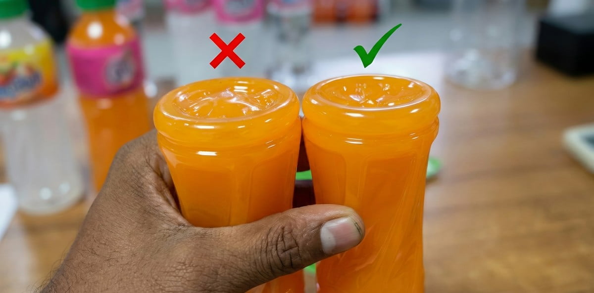
(Image description: PET bottles exhibiting center gate rollout, preventing the containers from standing vertically. This is a direct result of inadequate base mold cooling.)
Engineering Intervention:
If your current mold is already experiencing base bulging and instability, do not discard the tooling prematurely. Please read our troubleshooting guide: PET Bottle Base Rollout Analysis: A 6-Step Guide to Fixing Center Gate Bulging and Rocker Bottoms, to resolve the issue by adjusting your blow molding machine parameters. However, if you are preparing to customize a new mold, you must require the supplier to utilize conformal cooling channels in the contract to prevent this issue from the engineering source. Conformal cooling channels are machined to follow the exact 3D contours of the petaloid base, ensuring uniform thermal extraction.
5. CSD Molds vs. Filling Line Top-Load Requirements
Evaluating a CSD mold design exclusively on its blowing characteristics ignores the mechanical stress of the filling process. Counter-pressure filling valves exert significant downward force; the mold’s shoulder and neck support geometry must be engineered to resist this specific top-load pressure.
A critical integration oversight occurs when mold procurement is disconnected from filling line specifications. Carbonated beverages require isobaric (counter-pressure) cold filling systems. To prevent the loss of carbonation during filling, the filling valve descends and physically clamps onto the bottle, creating a pressurized seal before the liquid is dispensed.
This clamping action exerts substantial downward mechanical force, known as top-load, onto the neck support ring and shoulder of the container. If the mold design allocates insufficient material thickness to the shoulder area, or if the geometric angle of the shoulder is too shallow to distribute the downward force, the bottle will yield. The neck will crush or deform under the filling valve, leading to line jams, product spillage, and capping alignment failures.
To prevent this, your tooling supplier must be provided with the exact top-load resistance requirements mandated by your filling equipment manufacturer. The mold’s stretch profile must be calibrated to ensure adequate wall thickness remains in the upper third of the bottle. For further insights into neck alignment issues, refer to Caps Won’t Seal: A 6-Step Protocol to Fix PET Bottle Neck Deformation (Ovality).
Table 2: Force Dynamics by Filling Application
| Filling Technology | Internal Pressure | Top-Load Force Requirement | Critical Mold Design Area |
|---|---|---|---|
| Gravity Filling (Still Water) | Ambient | Low | Body panel rigidity |
| Hot Fill (Juice/Tea) | Vacuum (Post-cool) | Moderate | Vacuum compensation panels |
| Isobaric Filling (CSD) | High (Positive) | High | Shoulder angle & Neck support |
6. Case Study: Aluminum vs. S136 Stainless Steel Base Molds
Specifying standard aluminum for a CSD base mold accelerates corrosion due to severe condensation from internal cooling circuits. To maintain the precise geometry of the petaloid base over millions of cycles, the base insert must be machined from S136 anti-rust stainless steel.
In our factory history, we exclusively supply molds guaranteed to endure over 6 million blow cycles. A fundamental component of this longevity is material selection. A common procurement error is attempting to reduce tooling costs by allowing the supplier to manufacture the entire mold, including the base insert, out of standard aluminum.
While 7075-T6 aluminum is an optimal material for the main body cavities of a PET blow mold due to its high thermal conductivity and ease of CNC machining, the base mold operates under a significantly harsher environmental profile. The base block is subjected to the highest mechanical clamping impacts. More critically, because the petaloid base requires intensive circulation of chilled water to prevent rocker bottoms, the severe temperature differential between the cold base mold and the ambient factory air generates continuous surface condensation.
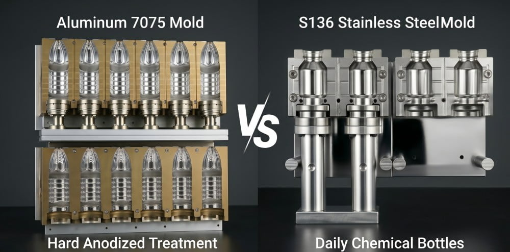
(Image description: Comparing the surface integrity of aluminum versus S136 stainless steel after exposure to cooling circuit condensation in a blow molding environment.)
If standard aluminum is utilized for the base, this continuous moisture exposure induces rapid surface oxidation and pitting. Once the precision geometry and air-venting clearances of the petaloid petals are compromised by corrosion, the mold will produce dimensionally inaccurate bases, rendering the tooling obsolete. We mandate the use of S136 mirror-polished, anti-rust stainless steel for all CSD base molds. This material provides the necessary hardness and corrosion resistance to maintain structural integrity. For a detailed breakdown of tooling materials, review Why Are Most PET Blow Molds Made of Aluminum? 4 Engineering Reasons Explained.
Table 3: Base Mold Material Comparison for CSD Tooling
| Material Characteristic | 7075-T6 Aluminum | S136 Stainless Steel |
|---|---|---|
| Primary Application | Mold body cavities | CSD Base inserts & Neck rings |
| Corrosion Resistance | Low (Susceptible to condensation) | Extremely High (Anti-rust) |
| Surface Hardness | Moderate | High (Resists clamping wear) |
| Long-Term Suitability | Inadvisable for CSD bases | Required for sustained CSD production |
7. FAQ: Custom CSD Bottle Mold Engineering
FAQ 1: Can I just add a petaloid base to my current flat water bottle design for CSD?
No, this is an inadvisable engineering practice. CSD bottles must withstand continuous high internal CO2 pressure. If you do not redesign the bottle body geometry—such as incorporating horizontal structural ribs or adjusting the shoulder curve—the internal gas pressure will deform the flat panels into a spherical shape, causing dimensional failure even if the petaloid base remains intact.
FAQ 2: Why does a CSD mold require a heavier preform than a standard water bottle?
The complex 5-petal or 6-petal design of a CSD base requires a significantly higher volume of PET material to form completely. Utilizing a lightweight preform will leave the deep crevices of the base starved of material, resulting in critically thin wall sections that will rupture under internal carbonation pressure.
FAQ 3: What causes "rocker bottoms" (bulging base), and how do your molds prevent it?
Rocker bottoms occur when the thick center injection gate of the PET preform does not cool rapidly enough inside the mold, leading to post-ejection thermal shrinkage that pushes the center outward. We prevent this by engineering complex conformal cooling channels into the S136 stainless steel base mold, ensuring the polymer sets rigidly before the bottle is ejected.
FAQ 4: Will the bottle mold design affect my performance on the filling line?
Yes. CSD processing involves counter-pressure cold filling, which exerts high downward top-load pressure from the filling valves. If your mold design lacks the calculated structural resistance in the neck support and shoulder angles, the bottles will yield or collapse under the filling machinery.
FAQ 5: Why do you insist on S136 stainless steel for the base mold instead of standard aluminum?
The base mold is highly prone to water condensation generated by the internal cooling circuits. Standard aluminum will rapidly corrode and pit in this environment. S136 stainless steel prevents rust and maintains its surface hardness, ensuring the complex geometry of the petaloid shape remains dimensionally accurate for over 6 million blowing cycles.
Are you planning to transition your packaging line to handle carbonated soft drinks? Ensure your tooling is engineered for the exact thermodynamic and structural demands of CSD production. Contact our engineering team at petmolder.com with your CO2 volume requirements and filling machine specifications, and we will provide a rigorous structural evaluation for your next mold project.
Further Technical Reading:
- PET Blow Mold Preventive Maintenance: A Complete Guide for Aluminum and Stainless Steel Tooling
- Custom Blow Molds: 4 Reasons Your New Mold Won’t Fit Your Blowing Machine
- Looking for a Preform Mould Maker in China? 5 Ways to Spot a Trader vs a Real Factory
- The Ultimate Guide to Preform Neck Finishes: How to Choose the Right Standard for Your Bottle
- From Concept to Production: What are the 8 Steps to Custom PET Bottle Molds?
-300x300.jpg)