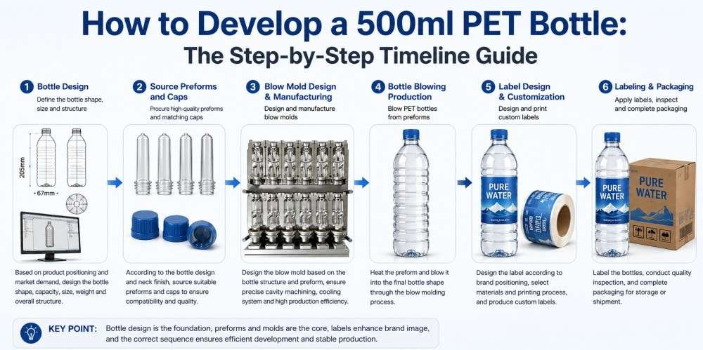
The process of developing a 500ml PET bottle requires a strict chronological sequence, beginning with filling line compatibility and theoretical preform weight calculation, progressing through physical sample verification of caps and preforms, and concluding with label sizing based on trial-blown physical bottles to ensure dimensional stability.
Recently, I received an inquiry from a new client in Argentina who was initiating a beverage project. Like many overseas buyers entering the packaging sector, this client was confused about the operational timeline. They simply requested a 500ml bottle design. In response, I asked a series of technical prerequisites: Have you determined the preform neck finish? What is the target preform weight? What are the specifications of your blow molding machine?
The client did not understand why a simple design required such extensive data. The engineering reality is that a PET bottle design does not exist in isolation. The geometric shape is structurally bound to the preform mass, the blowing equipment, and the downstream filling line. In my workshop in Guangdong, China—where we exclusively manufacture PET blow molds and operate from our facility established in 2010 (following the founding of our original mold workshop in 2004)—we mandate a strict chronological protocol for tooling projects. Reversing this sequence leads to severe dimensional incompatibility. Today, my technical team and I outline the exact step-by-step timeline for developing a standard 500ml PET bottle.
Step 1: Conceptualizing the Design and Matching the Filling Line
Initiating the bottle concept requires immediate verification of the downstream filling line specifications. The neck finish, such as 3025 or 28mm PCO, must align exactly with the pneumatic grippers and air conveyors of the filling equipment to prevent catastrophic mechanical jamming during continuous production.
Everything begins with the product concept, but the exterior shape is secondary to the mechanical interface. Before drafting any localized curves or structural ribs on a 500ml bottle, you must lock in the neck finish. In modern beverage production, the bottle is transported through the rinsing, filling, and capping block via air conveyors that support the container entirely by the neck ring.
If you design a bottle utilizing a 3025 neck finish, but your downstream filling machine is calibrated with star-wheels and grippers designed for a 28mm PCO 1881 standard, the line will fail to operate. The grippers will either crush the smaller neck or drop the bottles entirely. Overseas buyers frequently assume that neck finishes are interchangeable post-design. They are not. The neck finish dictates the internal mandrel size of the blow molding machine and the specific tooling required for the capping heads.
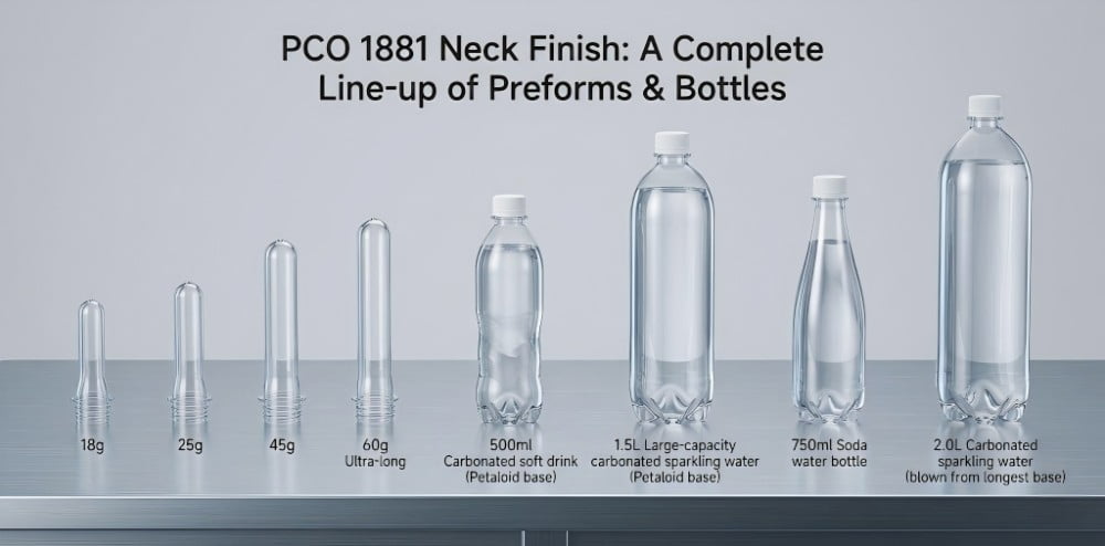
When we begin a project, we request the technical manual of the client's filling equipment. We evaluate the clearance required under the neck support ring and the total height restrictions of the filling valves. Only after these mechanical constraints are verified do we proceed to shape the cylindrical body. For a comprehensive breakdown of how blowing equipment dictates mold dimensions, review our analysis on why your new custom mold won't fit your blowing machine.
Step 2: Calculating the Theoretical Preform Weight
Following the conceptual design, the blow mold engineering team utilizes CAE software to calculate the theoretical preform weight. This mass determines the final wall thickness, directly impacting the container's top-load strength, logistics capability, and the overall resin expenditure of the production run.
Once the external geometry of the 500ml bottle is defined, we must determine how much polymer is required to form that specific shape. We employ Computer-Aided Engineering (CAE) software to calculate the total surface area of the 3D model. By applying standard industry wall thickness parameters (typically requiring a minimum of 0.25 mm in the main body for adequate rigidity), we reverse-engineer the theoretical preform weight.
For a standard 500ml water bottle, the baseline preform weight is generally 16 grams. However, this is not a fixed metric. I advise clients to adjust this weight based on their specific commercial and logistical strategies. If the product is subjected to long-distance export shipping and stacked multiple pallets high, a 14-gram preform will yield side walls that are too thin, causing the bottom layers to buckle under the vertical load. In this scenario, increasing the preform mass to 18 grams provides the necessary section modulus. Conversely, if the distribution is highly localized and budget-constrained, reducing the weight to 14 grams lowers resin costs, provided the geometric design incorporates deep horizontal ribs to compensate for the lost material rigidity.
To understand how material reduction affects structural integrity, consult our 7-step engineering guide to reducing weight safely.
500ml Preform Weight & Application Matrix
| Preform Weight | Wall Thickness & Rigidity | Top-Load Strength | Engineering Application |
|---|---|---|---|
| 14g | Thin and flexible | Low (Susceptible to denting) | Localized distribution, budget bottled water with deep ribbed designs. |
| 16g | Standard industrial baseline | Medium (Standard stacking) | Mainstream supermarket still water; balanced structural performance. |
| 18g+ | Highly rigid | Excellent (Resists vertical crushing) | Premium mineral water, long-distance shipping, or smooth-wall aesthetic designs. |
Step 3: Sourcing Preforms and Verifying Feasibility
Securing universal off-the-shelf preforms requires sending physical samples to the blow mold facility for feasibility analysis. Engineers must verify that the preform's axial length and radial stretch ratio accommodate the specific 500ml bottle geometry to prevent base thinning or material crystallization.
With the neck finish (e.g., 3025) and the target weight (e.g., 16g) established, the next phase is sourcing the actual preforms. Utilizing standard, off-the-shelf preforms from established injection molding suppliers is a highly efficient strategy that avoids the capital expenditure of developing custom injection molds.
However, locating a 16g, 3025 preform is only partial validation. You must send the physical preform drawing or the actual sample to our facility for mechanical evaluation. A preform is defined by its length, diameter, and wall thickness. If you select a preform that is excessively short for a tall, slender 500ml bottle design, the axial stretch ratio will exceed the polymer's natural limits. The stretch rod will push the material to the base, resulting in a dangerously thin bottom that will rupture upon filling.
Conversely, if the preform is too wide for a narrow bottle design, the radial stretch ratio will be insufficient. The material will not orient properly, leading to thick, heavy side walls and a highly inefficient thermal cooling cycle. We analyze these stretch ratios strictly. If the selected preform does not align with the thermal dynamics of the blowing process, we will mandate a modification to the bottle's height or diameter. Ignoring this step leads directly to the issues discussed in our guide on fixing center gate bulging and rocker bottoms.
Step 4: Sourcing Caps and the "Physical Sample Testing" Rule
Procuring caps from external suppliers demands mandatory physical sample testing. Buyers must physically thread the selected closure onto the specific preform sample to verify torque specifications and ensure a secure, watertight seal prior to authorizing bulk manufacturing.
Because our facility focuses exclusively on precision PET blow molds and does not manufacture closure molds, our clients source their caps from specialized injection facilities. A critical engineering rule in this phase is the mandatory physical integration test.
Never authorize bulk production based solely on matching standard nomenclature. Assuming a generic "3025 cap" will seal flawlessly on any "3025 preform" is a severe operational risk. Microscopic variations in thread pitch, clearance angles, and the inner plug seal diameter exist between different injection mold manufacturers. If the plug seal does not compress adequately against the inner wall of the preform neck, the final bottle will leak fluid and lose carbonation during transport.
We instruct our overseas clients to request minimum sample batches (e.g., 50 pieces) of both the preform and the cap. These components must be physically tested together using a torque meter to evaluate application and removal resistance. Only when the physical interference fit is validated should the purchasing department release the bulk order. To navigate these specifications accurately, refer to the ultimate guide to preform neck finishes.
Common Neck Finishes & Compatibility Guide
| Neck Finish Standard | Typical Neck Weight | Cap Type Needed | Recommended Beverage Application |
|---|---|---|---|
| 3025 | 1.8g - 2.0g | Short-plug water cap | Still water, pure mineral water. |
| 2925 | 1.2g - 1.5g | Ultra-light short cap | Eco-friendly lightweight still water lines. |
| 28mm PCO 1881 | 3.7g - 4.0g | Carbonation-safe cap | CSD (Carbonated Soft Drinks), sparkling water, pressurized juices. |
Step 5: Finalizing the 3D Design and Ordering the Mold
Upon verifying the physical preform and cap mechanics, the final 3D bottle design is locked, allowing for the initiation of blow mold manufacturing. The engineering team programs CNC toolpaths, compensating for the natural thermal shrinkage of PET to ensure exact volumetric capacity.
With all external variables secured—the filling line constraints, the preform mass, the stretch ratios, and the cap compatibility—we transition to the final 3D modeling and mold manufacturing phase. At this juncture, the design is locked. Altering the volume or the overall height after this point will invalidate the previous preform feasibility calculations.
The manufacturing of the blow mold requires strict metallurgical selection and high-precision machining. For standard and high-speed applications, we utilize Al 7075 aviation-grade aluminum for the main cavity halves to maximize thermal conductivity, paired with S136 stainless steel for the bottom mold inserts and neck rings to resist the continuous mechanical impact of the stretch rod and clamping forces. We explicitly avoid low-grade materials like P20 steel, as they lack the necessary rust prevention and thermal efficiency for modern blowing cycles.
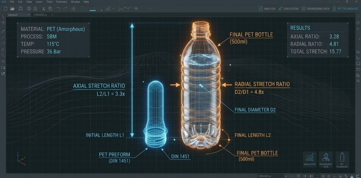
During the CNC programming phase, our engineers calculate the volumetric shrinkage. When PET transitions from a heated, amorphous state in the blow mold to a cooled, crystalline state on the conveyor, it undergoes volumetric contraction (typically between 1.0% and 1.5%). To guarantee the bottle holds exactly 500ml at the fill line, the actual mold cavity must be machined slightly larger than the target volume. This precision engineering is detailed in our overarching methodology: From concept to production: what are the 8 steps to custom PET bottle molds?.
Step 6: Trial Blowing to Get the Physical Bottle
The trial blowing phase provides the first physical realization of the 500ml container. This controlled production run verifies mold parting line tolerances, thermal cooling efficiency, and base formation, yielding the critical physical samples required for downstream packaging sizing.
After the CNC milling, polishing, and assembly processes are complete, the mold undergoes trial blowing. This is a critical validation step in the manufacturing timeline. We install the new blow mold into our testing equipment, input the specific 16g preforms the client sourced, and adjust the infrared heating profile and high-pressure blowing parameters.
The objective of trial blowing is not simply to produce a bottle, but to verify the mechanical integrity of the tooling. We inspect the container for uniform material distribution using ultrasonic thickness gauges. We evaluate the parting line to ensure the mold halves lock securely without allowing material extrusion under high pneumatic pressure.
Once the machine parameters are stabilized and the mold is validated, we produce a batch of physical sample bottles. These are not digital renderings; they are the tangible, thermally contracted end-products. These physical samples serve as the mandatory reference point for all subsequent packaging procurement. Proceeding to order labels or cartons before holding these physical samples introduces severe dimensional risk to the project.
Step 7: Sending the Physical Bottle for Label Customization
Forwarding the trial-blown physical bottles directly to the label manufacturer ensures exact dimensional matching. The label supplier utilizes the physical contours to calculate sleeve shrinkage rates and adjust the cutting die, eliminating the risk of wrinkling or misalignment during high-speed application.
A common operational error in cross-border procurement is ordering product labels based on the initial 3D digital drawings or relying on manual caliper measurements. Digital drawings represent the theoretical geometry; they do not account for the microscopic variations induced by thermal shrinkage or the slight outward expansion that occurs when the bottle is filled with liquid.
For applications utilizing shrink sleeve labels, the tolerance for error is minimal. The sleeve must pass over the widest part of the bottle and shrink uniformly into the narrowest grooves when exposed to the heat tunnel. If the label supplier calculates the thermal contraction rate based on a digital file, the resulting labels frequently arrive too loose, leading to severe wrinkling, or too tight, causing the label to tear during application.
The most secure engineering protocol is to package a minimum of 20 trial-blown physical bottles and ship them directly to the label printing facility. The supplier utilizes these exact physical samples to run a test application, adjusting their cutting dies and heat tunnel parameters to match the real-world geometry.
Label Sizing Risks: 3D Drawing vs. Physical Bottle
| Data Source for Label Design | Accuracy Rate | Hidden Risks in Mass Production |
|---|---|---|
| Using 3D Digital Drawings | Low | Thermal shrinkage is ignored; labels arrive too loose or misaligned on the production line. |
| DIY Manual Measurements | Medium | Micro-curves are missed; labels wrinkle during machine application due to inaccurate circumference data. |
| Sending Physical Bottles | Maximum Reliability | The label supplier custom-fits the die directly to the physical contour, ensuring precise application. |
Step 8: Finalizing Carton Dimensions and Mass Production
Finalizing carton dimensions requires arranging the trial-blown bottles into the intended physical array to measure exact external tolerances. This physical mapping guarantees the corrugated packaging provides rigid vertical support, preventing logistical damage before initiating continuous mass production.
The final step in the development timeline is finalizing the secondary packaging. Similar to the labeling protocol, calculating carton dimensions using theoretical bottle diameters leads to logistical failures. If the carton is too large, the bottles will shift and collide during transit, leading to scuffing and compromised top-load stability. If the carton is too tight, the automated case packer will crush the bottles during insertion.
To engineer the precise carton dimensions, we arrange the physical, liquid-filled sample bottles into the target configuration (for example, a 4x6 array for a 24-bottle case). We measure the exact external length, width, and height of this physical grouping, accounting for the minor radial expansion caused by the liquid mass. This data is transmitted to the corrugated box supplier to design a carton that fits securely, ensuring that the vertical load during palletization is transferred through the bottle columns rather than the cardboard walls.
Once the carton dimensions are locked, all mechanical and logistical components are verified. The blow mold is approved for shipment, and the client’s facility can initiate continuous mass production with the confidence that the preforms, caps, labels, and cartons operate as a cohesive, engineered system.
Step-by-Step Summary Matrix for 500ml Bottle Development
| Phase | Action Required | Engineering Purpose | Critical Checkpoint |
|---|---|---|---|
| Step 1 | Confirm Neck Finish & Volume | Match filling line equipment | Validate gripper and air conveyor compatibility. |
| Step 2 | Calculate Preform Weight | Define structural rigidity | Balance material cost against top-load requirements. |
| Step 3 | Source & Verify Preforms | Confirm stretch ratios | Ensure preform length fits the specific bottle design. |
| Step 4 | Procure & Test Caps | Guarantee leak-proof sealing | Conduct physical torque tests between cap and preform. |
| Step 5 | Finalize 3D & Order Mold | Initiate CNC machining | Compensate for PET thermal shrinkage in mold dimensions. |
| Step 6 | Execute Trial Blowing | Produce physical samples | Verify mold parting lines and material distribution. |
| Step 7 | Customize Labels | Ensure precise sleeve fit | Send physical bottles to label factory for die calibration. |
| Step 8 | Finalize Carton Sizing | Secure logistical transport | Measure physical bottle arrays for exact corrugated sizing. |
Frequently Asked Questions (FAQs)
Q1: Why should I determine the bottle design before buying the preform?
The geometric bottle design dictates the volume and radial requirements. Once you establish a concept, a mold factory calculates the optimal theoretical preform weight and length. If you purchase preforms blindly beforehand, they will likely lack the correct stretch ratio to form your specific design, leading to localized thinning or base ruptures.
Q2: Can I just choose the lightest preform to save money on my 500ml bottles?
While reducing the preform weight (e.g., from 16g to 14g) lowers material expenditures, it directly decreases the bottle's wall thickness and top-load strength. You must carefully balance cost-saving objectives with the physical demands of your distribution logistics and warehouse stacking requirements.
Q3: Is it safe to buy caps and preforms from different suppliers?
Yes, but you must adhere to a strict operational rule: always request physical samples of both components before placing bulk orders. You must physically test them together using torque measurement to ensure the threads engage accurately and form a watertight seal, avoiding severe production downtime or severe leakage.
Q4: Do standard off-the-shelf preforms work for custom bottle designs?
Most universal off-the-shelf preforms are highly compatible with standard custom designs. However, it is mandatory to have your blow mold manufacturer evaluate the physical preform sample or drawing. They verify that the axial length and stretch ratio are suitable for blowing your specific 500ml shape without causing structural weak points.
Q5: Why must I wait until trial blowing is finished to order my bottle labels?
PET plastic undergoes volumetric shrinkage after it is blown and cools. The dimensions on your digital 3D engineering drawing will not match the final physical bottle exactly. Sending the actual trial-blown bottle to the label factory allows them to measure the physical contours accurately, ensuring mass-printed labels fit flawlessly without wrinkling.
Related Technical Guides:
- From Concept to Production: What Are the 8 Steps to Custom PET Bottle Molds?
- Custom Blow Molds: 4 Reasons Your New Mold Won't Fit Your Blowing Machine
- The Ultimate Guide to Preform Neck Finishes: How to Choose the Right Standard for Your Bottle
- PET Bottle Lightweighting: A 7-Step Engineering Guide to Reducing Weight Safely
- PET Bottle Base Rollout Analysis: A 6-Step Guide to Fixing Center Gate Bulging