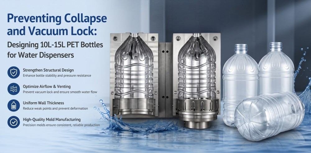
Designing 10L-15L one-way PET bottles for water dispensers requires engineering structural resistance against atmospheric pressure. By integrating deep horizontal ribs for hoop strength, controlled-collapse geometries, and precision neck tolerances, manufacturers mitigate vacuum lock. This ensures continuous water flow while maintaining economical preform weights between 300g and 350g.
In my workshop, I frequently discuss the physics of large-format PET packaging with overseas factory owners. Transitioning from rigid, returnable Polycarbonate (PC) jugs to one-way, single-use PET bottles introduces complex mechanical challenges. The primary issue is dimensional stability under negative internal pressure. When placing a high-capacity PET bottle onto a standard water dispenser, gravity draws the liquid downward. If ambient air does not enter the container to replace the displaced fluid volume, a severe internal vacuum is generated. Overcoming this physical phenomenon requires precise structural manipulation within the blow mold design.
1. The Physics of Vacuum Lock: Why One-Way PET Bottles Collapse on Dispensers
Vacuum lock occurs when fluid exits a sealed 10L-15L PET bottle without air displacement, generating severe negative internal pressure. Because the structural rigidity of a 300g-350g preform cannot withstand external atmospheric pressure, the thin side walls yield inward, choking the fluid channel and halting water flow.
To understand the mechanical behavior of large-capacity one-way packaging, we must analyze the interaction between fluid dynamics and polymer limitations. A traditional 5-gallon PC jug features thick walls (often exceeding 700g of material), providing sufficient section modulus to resist external atmospheric pressure. As water exits the PC jug, the rigid walls force air bubbles to pull through the dispenser probe to equalize the internal pressure.
One-way PET bottles are engineered for extreme lightweighting to reduce single-use plastic consumption and lower shipping costs. A typical 15L PET bottle utilizes a preform weight ranging from 300g to 350g. At this mass, the radial stretch ratio results in extremely thin side walls. When the water begins to dispense, the internal pressure drops below standard atmospheric pressure (101.3 kPa). The external atmospheric pressure continuously exerts an inward force across the massive surface area of the 15L cylinder.
Because the thin PET walls possess low inherent compressive strength, they buckle inward before the vacuum pressure is high enough to pull air bubbles up through the water column. As the walls collapse inward, they fold and pinch the internal geometry, physically blocking the downward flow of water. This mechanical stalling is known in the industry as vacuum lock. Understanding how internal volume and pressure interact is critical, a concept we explore further in our PET bottle volume shrinkage analysis.
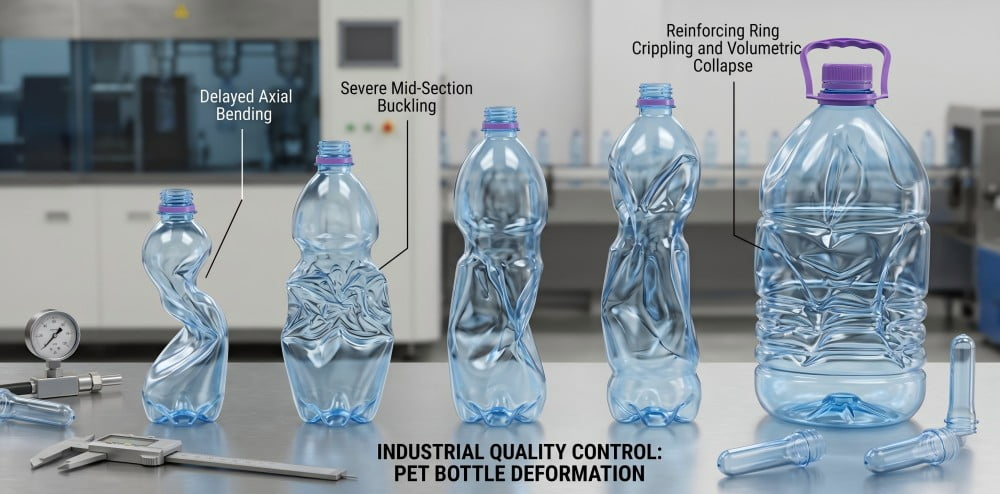
Severe side-wall yielding under negative internal pressure disrupts the structural integrity of the container, ultimately halting fluid displacement.
2. Maximizing Hoop Strength: Engineering Deep Horizontal Ribs
Maximizing hoop strength involves engineering dense, deep horizontal ribs along the cylindrical axis of the bottle. These structural indentations act as continuous reinforcement rings, significantly increasing the lateral compressive resistance of the thin PET wall to delay the onset of vacuum-induced collapse.
When engineering a large-capacity container to resist external pressure, the primary geometric strategy involves manipulating hoop stress. In a smooth-walled cylinder, any negative internal pressure causes immediate localized buckling. To counteract this, we design the blow mold with deep horizontal ribs.
These ribs function mechanically similar to steel hoops on a wooden barrel. By creating a corrugated profile, the moment of inertia of the side wall increases exponentially. When atmospheric pressure pushes inward, the deep ribs distribute the compressive force along their horizontal circumference, maintaining the circular cross-section of the bottle for a longer duration.
However, designing these ribs requires strict calculation of the radial stretch ratios. If the ribs are too deep or the transition angles too sharp, the PET material will thin out excessively at the inner radii, creating weak points that paradoxically accelerate collapse. We typically recommend utilizing specialized CAE (Computer-Aided Engineering) software to map the stress distribution before finalizing the mold cavity.
| Structural Element | Mechanical Function | Design Specification for 15L PET |
|---|---|---|
| Rib Depth | Increases section modulus against inward force. | 4.0mm to 6.5mm, depending on preform mass. |
| Rib Spacing (Pitch) | Distributes atmospheric load evenly. | 25mm to 40mm intervals along the body. |
| Transition Radius | Prevents localized material thinning. | Minimum R1.5mm to R2.5mm to ensure smooth polymer flow. |
| Vertical Panels | Prevents axial elongation under vertical load. | Intersecting vertical supports to stabilize the ribs. |
3. The "Controlled Collapse" Strategy: Origami-Style Geometries for Continuous Flow
The controlled collapse strategy guides the inevitable deformation of the lightweight PET bottle through pre-determined geometric folding lines. By molding accordion-style structural grooves, the container compresses vertically and symmetrically, ensuring the internal water channel remains unobstructed until the bottle is empty.
Relying exclusively on hoop strength presents physical limitations; eventually, a 300g 15L bottle will yield to continuous negative pressure. A highly advanced engineering alternative is the "controlled collapse" or accordion-style design. Instead of attempting to build an impenetrable wall, this structural geometry accommodates the vacuum by guiding how the bottle compresses.
By machining specific diagonal or horizontal folding grooves into the mold cavity, the bottle acts as an engineered bellows. As the water volume decreases and the vacuum increases, the bottle is structurally programmed to fold inward in a highly organized, symmetrical manner—typically from the top shoulder downward.
This organized folding prevents the side walls from twisting randomly and pinching the center axis. The fluid column remains continuous and unblocked, allowing the dispenser to extract nearly 100% of the liquid. I advise overseas buyers that designing these origami-style geometries requires exceptional precision in the CNC machining phase, as the angles of the structural creases dictate the exact sequence of deformation.
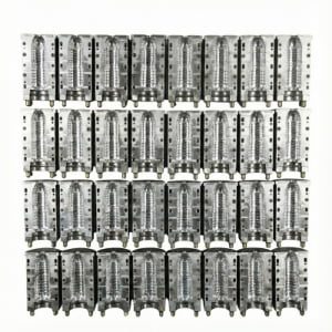
Large-capacity blow molds require intricate structural programming on the cavity walls to dictate how the final container handles internal negative pressure.
4. Shoulder and Base Reinforcement: Preventing Cracks During Deformation
When a 15L bottle undergoes vacuum deformation, mechanical stress concentrates intensely at the shoulder and base transitions. Optimizing the base push-up angle and the shoulder radii ensures these regions maintain their integrity, confining the structural yielding to the pre-designed side-wall panels.
Whether utilizing deep ribs or controlled-collapse geometries, the continuous deformation of a 15L bottle generates high levels of mechanical stress. This stress migrates to the stiffest parts of the container: the base and the shoulder. If the material distribution in these areas is suboptimal, the continuous flexing will lead to stress cracking and catastrophic water leakage on the dispenser.
During the blow molding process, the preform is stretched axially by the stretch rod and radially by high-pressure air. The base of a 15L bottle must endure the static weight of the water (approximately 15 kg) during transport, and then act as a stable upper dome when inverted on the dispenser. The support angle of the base push-up must be designed to absorb these dynamic loads. A shallow push-up will invert or bulge outward, destabilizing the container. For detailed mechanics on base geometry optimization, refer to our PET blow mold design guide for preventing base stress cracking.
Furthermore, the transition from the cylindrical body to the conical shoulder must feature generous R-corners (radii). Sharp angles at the shoulder act as stress risers. When the bottle compresses, a sharp shoulder will crack due to polymer fatigue. The mold must distribute a slightly thicker layer of amorphous PET to the shoulder zone to reinforce the structural transition.
5. The Interface: Optimizing the Neck Finish for Dispenser Probes
The neck finish of an inverted 15L bottle endures over 15 kg of vertical gravity and severe friction from the dispenser probe. Precision mold engineering ensures the neck ring tolerances allow for secure sealing and smooth probe insertion without inducing micro-cracks in the threaded region.
The physical interface between the PET bottle and the water dispenser is the neck finish. In a standard upright beverage bottle, the neck solely accommodates the closure. In a dispenser application, the neck is inverted and bears the entire dynamic load of the water column while interacting with the dispenser's internal probe (the spike that punctures the cap).
This interaction demands rigorous dimensional control during both preform injection and blow molding. The neck support ring (the flange below the threads) rests on the dispenser receptacle. If the perpendicularity between the neck finish and the bottle's vertical axis deviates by more than a fraction of a degree, the 15 kg mass will apply asymmetrical shear force to the neck, leading to severe bending or localized fracturing.
Additionally, the internal diameter of the neck must remain perfectly concentric. When the dispenser probe pushes through the non-spill cap, it displaces plastic and generates outward radial force. If the preform neck has crystallized or deformed slightly due to inefficient oven cooling shields, the probe insertion will crack the PET. To maintain strict neck dimensions and prevent sealing failures, we utilize protocols detailed in our guide: Caps won't seal? A 6-step protocol to fix PET bottle neck deformation.
| Interface Component | Mechanical Load | Engineering Requirement |
|---|---|---|
| Neck Support Ring | >15 kg vertical compression. | Thicker cross-section; strict perpendicularity to the main axis. |
| Internal Bore | Outward radial expansion from probe. | Zero ovality; precise thermal protection during heating. |
| Thread Profile | Rotational torque and axial pull. | High structural rigidity; smooth parting line transition. |
| Shoulder Transition | Bending moment from inverted weight. | Gradual polymer thickening from body to neck ring. |
6. Beyond the Bottle: The Critical Role of Air-Return Valve Caps
While structural bottle geometries delay collapse, physical limits remain for lightweight large-capacity packaging. Utilizing air-return valve caps introduces ambient air at the precise rate of fluid displacement, equalizing internal pressure, eliminating the vacuum effect, and guaranteeing continuous downward flow.
It is a mechanical reality that modifying the PET body structure provides finite resistance against atmospheric pressure. For ultra-lightweight 15L containers, relying entirely on the bottle wall to fight the vacuum is mathematically inefficient. The most definitive engineering solution requires modifying the closure system rather than just the bottle.
An air-return valve cap (or smart non-spill cap) features an integrated, one-way micro-silicone valve or mechanical labyrinth. When the bottle is inverted on the dispenser and water is drawn from the tap, the internal pressure drops. Instantly, the differential pressure forces the micro-valve open, allowing ambient air to flow into the bottle.
Because air enters the container at the exact volumetric rate that water exits, the internal pressure remains in equilibrium with the external atmosphere. The vacuum effect is neutralized at the source. This allows factory owners to aggressively reduce the preform weight (e.g., dropping from 350g to 310g) without fearing bottle collapse, as the PET wall no longer needs to function as a rigid pressure vessel. Understanding closure compatibility is paramount, a topic we cover in the ultimate guide to preform neck finishes.
7. Machining the Mold: Overcoming PET Thinning in Deep-Rib Designs
Machining deep horizontal ribs or controlled-collapse grooves requires ultra-precise CNC milling and specialized mold venting layouts. Inadequate venting traps air, forcing the expanding PET to stretch excessively over sharp contours, resulting in localized thinning and stress whitening during the blowing cycle.
Translating a complex, collapse-resistant bottle design into a physical mold block presents specific manufacturing hurdles. The deep ribs and sharp folding creases required for structural integrity create challenging topographical variations inside the aluminum mold cavity.
During the blowing phase (which operates at 30 to 40 bar pressure for large volumes), the heated PET must wrap tightly around these internal peaks and valleys. If the mold lacks a highly calculated venting system, the air trapped in the deepest recesses of the ribs cannot escape quickly enough. This trapped air acts as a pneumatic cushion, preventing the PET from fully contacting the cold mold wall. The plastic continues to stretch, becoming dangerously thin at the rib apex, and frequently crystallizes, resulting in a structural defect known as pearlescence.
To overcome this, our facility engineers utilize multi-axis CNC machining centers to cut precise micro-venting channels (typically 0.05mm to 0.08mm in depth) directly into the rib corners and parting lines. This allows instantaneous air evacuation, ensuring uniform material distribution without thermal degradation. If you observe cloudy or white patches on complex geometric structures, review our 6-step troubleshooting guide for PET bottle pearlescence and white haze.
8. Cost vs. Performance: Balancing Preform Weight with Vacuum Resistance
Balancing manufacturing costs with structural performance requires utilizing CAE mold flow analysis to pinpoint the exact preform mass required. Increasing wall thickness enhances vacuum resistance but escalates resin expenditure, necessitating precise mathematical optimization to achieve a highly functional, economical 15L container.
In the highly competitive water packaging sector, profit margins are strictly tied to resin consumption. Factory owners frequently ask me to design a 15L mold that will not collapse but demand it runs on a 280g preform. This represents a mechanical contradiction. The structural modulus required to resist atmospheric pressure inherently demands a specific mass of polymer.
The engineering solution is to balance the equation through digital simulation. Before cutting aluminum, we employ Computer-Aided Engineering (CAE) and Finite Element Analysis (FEA) to simulate the blow molding process and the subsequent vacuum loading on the virtual bottle. By iterating different preform weights (e.g., 300g, 320g, 350g) against various rib depths and folding geometries, we can identify the critical threshold.
| Parameter | Preform Weight (300g) | Preform Weight (350g) | Engineering Trade-off |
|---|---|---|---|
| Material Cost (Per Unit) | Lower | Higher | Direct impact on operational margins. |
| Vacuum Resistance (No Valve) | Suboptimal | Moderate | Thicker walls delay buckling under internal negative pressure. |
| Required Bottle Geometry | Advanced Controlled-Collapse | Deep Horizontal Ribs | Lighter weights mandate highly complex mold machining. |
| Blowing Pressure Requirement | Standard | Elevated | Heavier preforms require higher pneumatic force for corner definition. |
We advise clients to avoid arbitrarily selecting a preform weight based solely on market pricing. The weight must support the structural geometry. By optimizing the design, factories can achieve substantial resin savings without compromising the end-user experience on the dispenser. For a deeper understanding of how material reduction strategies impact production safety, consult our 7-step engineering guide to PET bottle lightweighting.
Frequently Asked Questions (FAQs)
Q1: Why does water stop flowing from a 15L one-way PET bottle on a water dispenser?
As water dispenses, a vacuum forms inside the bottle. Thin-walled one-way PET bottles collapse under atmospheric pressure instead of naturally drawing air in like rigid PC bottles. When the internal vacuum pressure equals the water's downward weight, the flow stops completely, a phenomenon known as vacuum lock.
Q2: How can bottle design prevent vacuum lock without adding extra PET material weight?
Engineers use "controlled collapse" geometries. By molding specific accordion-like or origami-style grooves into the bottle walls, the bottle is guided to compress neatly from top to bottom as the water empties. This prevents the walls from folding randomly and pinching off the water flow.
Q3: Are deep horizontal ribs enough to stop a 10L PET bottle from collapsing entirely?
Deep horizontal ribs significantly increase the "hoop strength" of the bottle to resist initial vacuum pressure. However, for large 10L to 15L volumes, relying solely on ribs is often insufficient. It is highly recommended to pair strong structural ribbing with a specialized air-return valve cap for guaranteed continuous flow.
Q4: What is an air-return valve cap and why is it critical for dispenser bottles?
An air-return valve cap is a smart closure system that features a built-in, one-way micro-valve. It allows ambient air to enter the PET bottle at the exact same rate that water exits. This equalizes the internal pressure, completely eliminating the vacuum effect and preventing the thin bottle from collapsing.
Q5: What are the main blow mold machining challenges for these anti-collapse PET bottles?
Creating the deep ribs or origami structures required for vacuum resistance demands ultra-precise CNC machining and optimal mold venting. If the mold venting is poor or the cavity contours lack smooth transitions, the PET material will over-stretch, resulting in weak spots, whitening, or tearing during the high-pressure blow molding process.
Related Technical Guides:
- PET Blow Mold Design Guide: Preventing Bottle Stress Cracking via Base Geometry
- PET Bottle Volume Shrinkage Analysis: Why Did Your 500ml Bottle Drop to 498ml Overnight?
- The Ultimate Guide to Preform Neck Finishes: How to Choose the Right Standard for Your Bottle
- PET Bottle Pearlescence (White Haze): A 6-Step Troubleshooting Guide From Preform to Blow Mold
- PET Bottle Lightweighting: A 7-Step Engineering Guide to Reducing Weight Safely