Can a single production batch of PET blow molds produce bottles with a 30ml capacity variance? Yes, unexpected volume discrepancies frequently occur when machining multi-mold batches without strict CNC tool wear management and CMM verification. Unmonitored cutting edge degradation shifts cavity dimensions, directly impacting filling line accuracy and fluid yields.
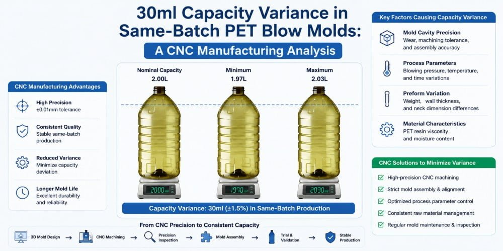
Last week, an urgent inquiry arrived from a beverage plant manager in South Africa. The client described a costly crisis: they had procured two identical PET blow mold sets intended for a 2L edible oil packaging line from a supplier in Zhejiang, China. When mounted on their blowing machines using identical preforms and process parameters, the bottles produced by the second mold set consistently yielded a volume of 1,970ml, while the first set produced the precise target volume of 2,000ml. This 30ml deficit created severe operational failures on their high-speed filling line. The liquid dispensers misjudged the headspace, causing edible oil to overflow and foul the exterior of the containers, triggering compliance risks and heavy financial losses. The client was frustrated, hesitant to re-order from their previous vendor, and seeking a definitive technical explanation of how identical engineering drawings could yield such a discrepancy.
When procuring molds, factory owners often mistakenly assume that matching numerical values on CAD drawings guarantee absolute physical dimensional consistency in the final machined metal parts. This is, in fact, a common engineering misconception; "precision" cannot be achieved through drafting alone but requires rigorous metrological inspection and dynamic machining compensation. Today, together with my technical team, I will conduct an in-depth analysis of the mechanical and metallurgical factors causing volume deviations in mold cavities within the same batch, and explain how professional mold manufacturers can effectively avoid these costly errors.
1. The South Africa Oil Bottle Crisis: Unraveling the 30ml Capacity Variance
An unexpected 30ml capacity variance in a 2000ml edible oil bottle destabilizes automated filling lines, resulting in overflow, liquid waste, and severe compliance discrepancies. In high-speed packaging, volumetric stability depends entirely on the micro-geometric precision of the aluminum or stainless steel mold cavity.
When a packaging line is engineered for a strict 2,000ml fill volume with targeted headspace, every single component must adhere to tight dimensional tolerances. Edible oil is viscous and sensitive to volumetric shifts. If the physical capacity of the container drops by 30ml to 1,970ml, the automated piston or flow-meter volumetric fillers pump the exact same quantity of oil into a smaller physical space.
The immediate result is liquid overflow during the filling sequence. The oil spills over the neck finish, coating the outside of the PET bottle, contaminating the labeling station, and gumming up the conveyor belts. Beyond the immediate packaging line mess, a 30ml under-volume on a 2L container violates commercial metrology regulations in many export and domestic markets. Consumers receive less product than labeled, exposing the brand owner to legal penalties and consumer distrust.
When the South African client first noticed the issue, they attempted to correct it by adjusting the blow molding machine parameters, modifying the pre-blow pressure, and altering the infrared oven heating profile to artificially "stretch" the plastic further. None of these machine-side adjustments resolved the discrepancy. The problem was not pneumatic; it was geometric. The physical boundaries of the mold cavity itself were constrained. To explore how volume shifts manifest under thermal stress, refer to our technical analysis on PET bottle volume shrinkage analysis.
2. Ruling Out Engineering Errors: Why Same-Batch Molds Are Not "Version Mistakes"
Investigating capacity discrepancies between same-batch molds rarely points to CAD drawing revisions. Professional mold manufacturers maintain strict version control systems, ensuring that repeat orders utilize identical digital parameters. The root cause of dimensional deviation is almost exclusively rooted in the CNC machining execution.
When buyers encounter physical discrepancies between two molds ordered simultaneously or sequentially under the same purchase order, their initial suspicion often falls on the design department. They assume the engineering team modified the 3D model between machining the first mold block and the second.
In professional mold manufacturing facilities, this scenario is virtually impossible. Modern manufacturing relies on centralized CAD/CAM databases. Once a client approves a 3D model for a custom edible oil bottle—incorporating precise volumetric compensations for polymer thermal contraction—that exact digital file is locked. It serves as the master blueprint for all subsequent CNC toolpath programming.
If the digital file is identical, why does the physical cavity differ? The answer lies in the dynamic environment of the CNC milling center. Machining aerospace-grade aluminum or S136 stainless steel is a brutal physical process involving extreme cutting speeds, high thermal friction, and continuous mechanical stress. The digital file remains static, but the physical tools, machine spindles, and thermal baselines change over time. Directing blame toward the design software obscures the real variable: machine-side manufacturing control. For a comprehensive overview of the baseline steps required to move from concept to accurate metal cutting, review our guide on from concept to production: what are the 8 steps to custom PET bottle molds?.
3. The Root Cause: CNC Tool Wear and "Cavity Shrinking"
Microscopic tool wear during high-speed CNC milling is the primary physical driver of cavity dimension reduction. As carbide cutting edges experience friction over prolonged machining hours, micro-chipping occurs, leaving slightly more metal inside the second mold block and resulting in a smaller physical volume.
To understand how a 30ml error occurs, we must examine the physics of CNC metal cutting. When machining a complex, multi-axis PET blow mold cavity—especially for contoured edible oil bottles featuring ergonomic gripping panels or smooth transition zones—mills operate at high RPMs for hours.
During the roughing and finishing passes of the first mold block, a brand-new carbide ball-end mill has pristine, razor-sharp cutting edges. It shears the aluminum or stainless steel precisely along the programmed toolpath, removing material down to the exact micron. However, carbide tools degrade gradually through abrasive friction and thermal fatigue. By the time the CNC machine finishes the first mold and immediately transitions to machine the second mold block within the same batch, the cutting edges of that same mill have experienced significant operational wear.
As the cutter's radius diminishes microscopically (often by just a few micrometers due to flank wear or micro-chipping), the tool deflects slightly under cutting loads. Instead of cutting deeply enough into the metal, the worn tool leaves a microscopic film of excess material along the interior walls of the mold cavity. When the two halves of this second mold close, the physical cavity volume is subtly reduced. In a large 2L container, shaving off even 0.2mm of internal radius across the entire surface area translates directly into a massive volumetric loss of 30ml.
| Machining Factor | First Mold Block (Fresh Tooling) | Second Mold Block (Worn Tooling) | Physical Consequence on Bottle |
|---|---|---|---|
| Cutting Edge Sharpness | Pristine, sharp carbide geometry | Micro-worn, radiused cutting edge | Incomplete material removal in cavity recesses. |
| Tool Deflection Rate | Minimal (< 0.005 mm deflection) | Noticeable under heavy cutting loads | Cavity walls remain slightly thicker inward. |
| Surface Finish (Ra) | Ultra-smooth mirror finish ($\le 0.1 \mu m$) | Minor micro-roughness or tool marks | Increased friction during blowing; reduced internal volume. |
| Volumetric Accuracy | Exact match to CAD master file | Reduced physical cavity space | 30ml capacity deficit in the final blown container. |
4. The Error Magnification Effect: How Microns Turn Into Milliliters
Small volumetric calculations in packaging engineering demonstrate that micro-scale dimensional errors on mold walls are multiplied across large internal surface areas. In a 2L container, an invisible inward shift of fractions of a millimeter compounds into a substantial 30ml liquid deficit.
Many overseas buyers struggle to comprehend how a machine error invisible to the naked eye can alter liquid capacity by 30 milliliters. The answer lies in volumetric geometry and surface area expansion.
Consider the mathematics of a 2L edible oil bottle. The internal surface area of the container is substantial. If a CNC milling cutter experiences flank wear, causing the finishing pass to leave an average of just 0.15mm to 0.25mm of excess metal across the entire internal perimeter of the cavity, that seemingly negligible thickness adds up. When the heated PET preform is inflated inside this restricted cavity during high-pressure blowing, the polymer cannot expand to its intended theoretical boundary.
The container is geometrically constrained. Because the internal radius of the bottle is fractionally smaller from top to bottom, the total volumetric capacity drops exponentially. This error magnification effect is particularly pronounced in large-capacity containers ranging from 2L to 5L. For a deeper examination of how dimensional variations impact volumetric integrity over time, review our analysis on PET bottle volume shrinkage analysis.
5. Dangerous Remediation: The Hidden Dangers of Manual Polishing
Attempting to correct cavity sizing errors through aggressive manual hand-polishing introduces geometric asymmetry. When technicians manually grind mold walls to expand volume, they inadvertently destroy the uniform parting line tolerances and create localized wall thinning in the final PET bottles.
When a non-standard or poorly managed factory realizes that a freshly machined mold cavity is producing under-volume bottles due to tool wear, unskilful workshops often resort to manual remediation. They instruct polishing technicians to use rotary abrasive tools to grind out the interior walls of the aluminum or stainless steel cavity to "expand" the volume.
This practice represents a severe quality control violation. Manual hand-polishing cannot replicate the precision of a 5-axis CNC machining center. Grinding by hand removes metal unevenly. One side of the cavity may be over-polished, while an opposing quadrant remains untouched.
This asymmetry destroys the concentricity and uniform material distribution of the bottle. When a preform is blown into an unevenly ground cavity, the plastic stretches erratically. The areas where excess metal was manually removed will feature overly thin walls, making the bottle structurally weak and susceptible to environmental stress cracking. Furthermore, altering the parting line edges manually leads to pneumatic leakage during high-pressure blowing. To understand the strict precision required for mold interfaces, review our guide on custom blow molds: 4 reasons your new mold won't fit your blowing machine.
6. Critical Quality Control Failures: The Absence of Pre-Shipment Metrology
The root cause of receiving mismatched mold sets is the absence of rigorous pre-shipment metrology and closed-loop testing. Without Coordinate Measuring Machine (CMM) verification and actual water-weight trial logging, manufacturing defects escape the workshop floor and inflict severe financial damage on overseas buyers.
The South African client's financial loss was not merely caused by a worn CNC cutting tool; it was enabled by a complete breakdown in the factory's internal quality control protocol. Machining errors happen in every engineering facility worldwide. The defining difference between a low-tier workshop and a top-tier manufacturer is the quality gate that intercepts those errors before dispatch.
In an unverified facility, molds are removed directly from the CNC milling machine, roughly cleaned, packed into wooden crates, and shipped. There is no intermediate inspection. Conversely, a professional mold manufacturing facility enforces strict metrology checkpoints.
Before any mold leaves our Guangdong facility, every single cavity undergoes CMM inspection to map its 3D geometry against the master CAD file. More importantly, we do not rely solely on digital coordinate data. We install the mold into a testing blow molding machine, run actual preforms matching the client's specifications, and conduct a physical volumetric verification test. If a mold fails to hit the exact target capacity, it is rejected immediately in the workshop. For a detailed checklist of what professional inspection entails, review our guide on PET preform mold FAT checklist: how to inspect a 48-cavity mold before delivery.
7. Advanced Solutions: Tool Life Management and Digital Manufacturing
Top-tier mold manufacturing facilities eliminate same-batch variance through automated Tool Life Management (TLM) systems and synchronized CNC machining protocols. By tracking cutting edge degradation via software and maintaining strict thermal baselines, advanced plants guarantee absolute dimensional replication.
To ensure that the 1st mold set and the 10th mold set in a multi-unit production order maintain absolute volumetric parity, leading manufacturing plants integrate advanced digital systems into their workshop floor operations.
The primary technological safeguard is Tool Life Management (TLM) integrated within the facility's Manufacturing Execution System (MES). The CNC milling center is programmed to monitor the exact cutting distance and operational time of every individual cutting tool. Long before a carbide mill reaches the threshold of micro-chipping or dimensional drift, the machine software triggers an automatic alert, forcing the operator to swap the worn tool for a fresh, identical backup cutter.
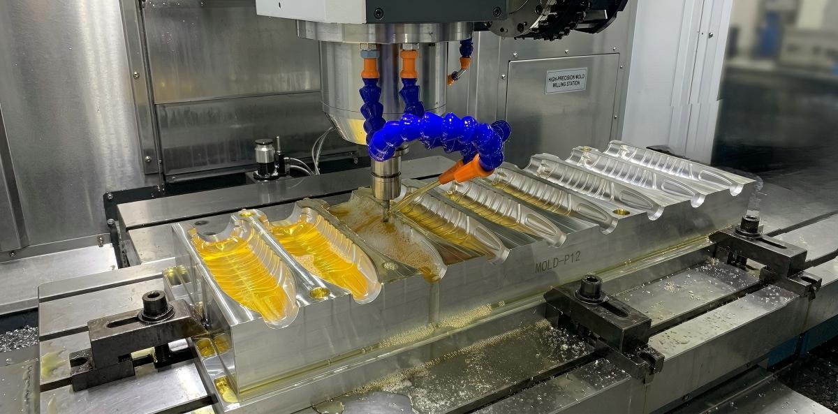
Advanced multi-axis CNC machining centers utilize automated tool life tracking to prevent dimensional drift across large production batches.
Furthermore, professional facilities control environmental and machine thermal stability. During long machining sessions, CNC machine spindles generate heat that causes thermal expansion of the steel components and ball screws. If a machine runs continuously for 24 hours, the thermal growth can shift zero points by several micrometers. Top-tier facilities utilize spindle thermal compensation algorithms and climate-controlled workshops, ensuring that the ambient temperature remains locked at 20°C. This guarantees that whether a mold block is cut at midnight or noon, the physical dimensions remain identical.
8. Procurement Checklist: Essential Verification Steps for Overseas Buyers
Mitigating the risk of receiving inconsistent mold batches requires enforcing a strict pre-shipment verification protocol. Overseas buyers must mandate single-cavity CMM inspection reports, trial blowing parameter logs, and unedited video proof of the water-weight verification test before authorizing final balance payments.
To protect your packaging lines from costly volumetric discrepancies like the one experienced by our South African client, you must integrate stringent verification checkpoints into your procurement contracts. Do not leave mold quality to chance.
Before issuing final payment for custom blow molds, require your supplier to provide verifiable proof of performance. A professional manufacturer will readily comply because they already execute these tests as part of their standard quality management system.
| Verification Stage | Action Required by Overseas Buyer | Acceptable Technical Standard |
|---|---|---|
| 1. Digital Sign-off | Review pre-machining 3D toolpaths and shrinkage data. | Explicit confirmation of PET thermal contraction compensation (1.0% - 1.5%). |
| 2. Metrology Audit | Request CMM (Coordinate Measuring Machine) inspection reports. | Dimensional deviation strictly controlled within $\pm 0.01\text{ mm}$ tolerance limits. |
| 3. Physical Trial Log | Obtain trial blowing parameter sheets and preform match data. | Verified execution using client-specified preform weight and neck finish. |
| 4. Volumetric Proof | Require unedited video of the "water-weight" test. | 100% volumetric match verified via water density conversion ($1\text{g} = 1\text{ml}$). |
By enforcing this checklist, you eliminate the risk of receiving mismatched tooling. If you are currently evaluating suppliers and need assistance identifying trustworthy manufacturing partners, review our technical checklist on looking for a preform mould maker in China? 5 ways to spot a trader vs. a real factory.
Frequently Asked Questions (FAQs)
Q1: Can blowing machine process parameters (such as air pressure or oven temperature) compensate for a 30ml mold capacity error?
Adjustment space on the machine side is strictly limited. While increasing pre-blow pressure or thermal exposure can marginally alter the stretching dynamics of a PET preform, the physical boundaries of the aluminum or stainless steel mold cavity dictate the absolute maximum volume of the container. Attempting to force machine parameters to stretch a restricted mold cavity results in uneven wall thinning, severe internal stress, and premature bottle bursting.
Q2: How frequently should CNC cutting tools be replaced when machining aluminum or stainless steel blow molds?
Tool replacement intervals are governed by material hardness and cutting distance rather than arbitrary time estimates. When milling aerospace-grade aluminum (Al 7075), cutting tools maintain integrity longer, but high-speed finishing passes still require programmed tool changes after specific linear cutting thresholds. When milling hard S136 stainless steel (hardened to 48-52 HRC), cutting edges degrade rapidly, necessitating frequent, automated tool swaps to prevent micro-deflection and dimensional variance.
Q3: What is the most reliable remote method for a buyer to confirm mold volume accuracy before shipment?
The industry standard for remote validation is the "water-weight test" video verification. The manufacturer must take a trial-blown sample bottle produced from the specific mold, place it on a calibrated electronic scale, tare the scale to zero, and fill the container with pure water up to the overflow point. Using the universal density standard where $1\text{g}$ equals $1\text{ml}$, the scale reading confirms the exact volumetric capacity. Buyers should demand an unedited, continuous video recording of this test.
Q4: Do multi-cavity blow molds (such as 1-out-of-4 or 1-out-of-8 configurations) suffer from individual cavity volume variances?
Yes, multi-cavity molds are particularly vulnerable if the facility lacks strict machining controls. If a CNC center machines multiple cavities on a single master mold block and the cutting tool experiences progressive wear from the first cavity to the last, the final cavities will feature reduced physical dimensions. This results in inconsistent bottle volumes across different cavities on the exact same production run.
Q5: Why is a 30ml volumetric error catastrophic on a 2L edible oil bottle while remaining less noticeable on a small 330ml water bottle?
The discrepancy stems from geometric scale and error magnification. A microscopic tool wear error of 0.15mm distributed across the massive internal surface area of a 2L container accumulates into a massive 30ml volumetric deficit. On a small 330ml water bottle, that exact same machining deviation would result in a negligible liquid variance of only 2 to 3 milliliters, which easily falls within standard packaging tolerance limits.
Conclusion and Engineering Summary
Summary Matrix: Same-Batch Mold Volume Variance vs. Precision Manufacturing
| Operational Metric | Unverified / Low-Tier Workshop | Professional Manufacturing Facility |
|---|---|---|
| CNC Tool Monitoring | Manual operator observation; high risk of undetected wear. | Automated Tool Life Management (TLM) via MES software. |
| Dimensional Inspection | Visual check only; frequent reliance on manual hand-grinding. | Full CMM (Coordinate Measuring Machine) mapping and reporting. |
| Volumetric Validation | None; relies entirely on digital CAD drawing assumptions. | Physical trial blowing and strict "water-weight" verification testing. |
| Batch Consistency | High risk of dimensional drift and 30ml+ capacity discrepancies. | Guaranteed physical parity across all molds within the production batch. |
Related Technical Guides:
- PET Bottle Volume Shrinkage Analysis: Why Did Your 500ml Bottle Drop to 498ml Overnight?
- From Concept to Production: What Are the 8 Steps to Custom PET Bottle Molds?
- Custom Blow Molds: 4 Reasons Your New Mold Won't Fit Your Blowing Machine
- PET Preform Mold FAT Checklist: How to Inspect a 48-Cavity Mold Before Delivery
- Looking for a Preform Mould Maker in China? 5 Ways to Spot a Trader vs. a Real Factory