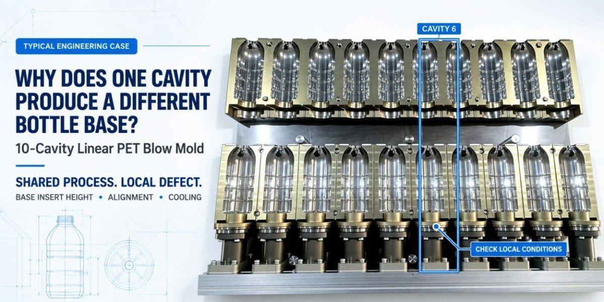
When nine cavities in a 10-cavity linear PET blow mold produce consistent bottles but one fixed cavity repeatedly makes a different bottle base, the first investigation should normally focus on that cavity’s local tooling condition rather than changing the shared blowing recipe. The effective base-forming position, alignment, assembly datum, cooling, venting, and local mold condition can all create cavity-to-cavity differences.
This distinction is important because all ten bottles may be produced in the same machine cycle, using the same batch of preforms and the same general blowing parameters.
If only one cavity remains different after repeated cycles, the most useful question is no longer:
“Which process parameter should we change?”
It becomes:
“What is physically different at this cavity?”
That change in diagnostic direction can prevent a factory from moving nine good cavities away from an already stable process window just to compensate for one local tooling problem.
Typical Engineering Example: Why Cavity #6 Produced a Different Bottle Base
Consider a 10-cavity linear PET blow mold in which cavities #1–#5 and #7–#10 repeatedly produce similar bottle bases, while cavity #6 shows a different push-up depth and standing geometry. Because the abnormality follows one fixed cavity, local mold geometry and assembly should be investigated before the common process is changed.
The following is an illustrative engineering scenario rather than a PETMOLDER customer case.
A PET bottle producer installs a 10-cavity linear blow mold for a beverage bottle. During the first production trials, the operators notice that nine bottles look nearly identical, but the bottle from cavity #6 has a slightly different base.
The difference is not dramatic enough to stop the machine immediately.
However, when the ten bottles are placed side by side, the #6 bottle repeatedly shows a different base depth. The center push-up appears slightly different, and the relationship between the standing ring and the surrounding heel is not exactly the same as the other nine bottles.
The production team initially considers changing preform heating and final blowing pressure.
That is a natural reaction because both parameters can influence bottle-base formation.
But there is an immediate problem with that strategy.
The heating and blow parameters are shared process conditions. Changing them to improve cavity #6 will also change the conditions seen by the nine cavities that are already producing acceptable bottles.
Instead, the team keeps the cavity identification for several consecutive cycles.
Bottle #6 remains different.
Bottle #1 remains normal.
Bottle #2 remains normal.
The same pattern repeats across the remaining cavities.
This repetition changes the diagnosis.
The defect is not randomly moving between cavities, and it is not affecting all ten bottles together. The abnormality is following one physical cavity.
The next inspection therefore moves to the local tooling around cavity #6.
The effective position of the base-forming surface is compared with the other cavities using the same mechanical reference. The inspection finds that the assembled forming position at cavity #6 is not consistent with the surrounding cavities.
This type of difference can result from the base component itself, but it can also come from the way the component sits in the mold. A small burr, contamination on a datum surface, incomplete seating, local damage, or a difference in the installation stack can change the final position even when the loose parts appear similar on the inspection table.
The important lesson is:
The blowing process is shared by all ten cavities, but the local tooling condition belongs to each cavity individually.
Why Can One Cavity Be Different When All Ten Cavities Share the Same Process?
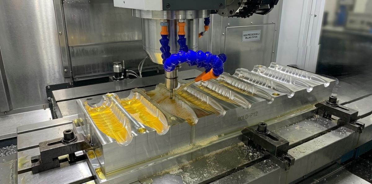
A multi-cavity linear blow mold shares many process conditions, but each cavity still has its own local forming surfaces, base interface, assembly condition, cooling path, and venting details. Shared process settings therefore do not guarantee that every local tooling condition is mechanically identical.
During one blowing cycle, the ten preforms experience the same general machine sequence.
They are reheated under the same oven system. They enter the same blow station. Pre-blow and high-pressure blowing occur according to the same machine recipe. The overall cycle time is shared.
This makes a multi-cavity mold very useful for diagnosis.
If all ten bottles begin showing the same change at approximately the same time, a common variable deserves immediate attention.
The preform batch may have changed.
The oven condition may have shifted.
The blowing pressure may be unstable.
The cooling-water temperature may have changed.
The machine recipe may have been modified.
However, when a fixed cavity repeatedly produces a different result while the other nine remain consistent, the probability of a purely common-process explanation becomes lower.
| Defect Pattern | More Useful First Diagnostic Direction |
|---|---|
| All ten cavities change together | Shared heating, preform, blow process, machine or utility condition |
| One fixed cavity repeatedly differs | Local tooling, assembly, cooling, venting or cavity geometry |
| Defect moves randomly between cavities | Process stability, preform variation, heating or handling |
| One cavity becomes abnormal only after maintenance | Assembly, local component installation or maintenance condition |
| One cavity changes gradually over time | Local wear, contamination, cooling restriction or vent blockage |
This does not mean that the process can never affect only one cavity.
A local cavity can be more sensitive than the others. A marginal cooling circuit or local geometry difference may make that cavity respond first when a common process changes.
But cavity tracking still gives us the correct starting point.
Cavity tracking tells us where to investigate. The defect pattern helps tell us what to investigate.
This same cavity-to-cavity logic was also important in our analysis of capacity variation within the same batch of PET blow molds, where small geometric differences can become measurable bottle-volume differences after blowing.
What Does “Base Mold Height” Actually Mean in a 10-Cavity Linear Blow Mold?
For a multi-cavity linear mold, “base height” should refer to the final assembled position of each effective bottle-base forming surface relative to a common mold datum. Measuring only the loose base component can miss installation and assembly differences that change the real cavity geometry.
This is one of the most important technical distinctions in this type of troubleshooting.
A technician may remove two base components, place them on a surface plate, measure their total heights, and find that they are almost identical.
That does not automatically prove that the two cavities create the same base geometry after assembly.
What matters to the PET bottle is not the loose component sitting on an inspection table.
What matters is where the actual forming surface is located when the blow mold is fully assembled and closed.
For cavity #1, there is an effective base-forming position relative to the common mold structure.
Cavity #2 has the same requirement.
The same is true through cavity #10.
If cavity #6 sits slightly higher or lower relative to that shared reference, the PET sees a different final cavity shape.
That can change the push-up depth.
It can change the standing-ring relationship.
It can affect the heel transition.
It may slightly change the overall internal volume of the bottle.
In some bottle designs, the effect may also appear as a small finished-height difference depending on the way the base geometry interacts with the rest of the cavity.
For this reason:
Measure the assembled forming position—not only the loose component height.
This principle applies well beyond the bottle base.
Multi-cavity tooling should be evaluated as an assembled system. Individual part accuracy is necessary, but the customer ultimately produces bottles from the assembled mold, not from loose components measured separately.
Why Are the Assembly Datum and Seating Surfaces So Important?
A base component can be dimensionally correct and still create the wrong bottle geometry if it does not seat correctly in the mold. The datum surfaces, locating features, contact faces, fasteners, and installation condition determine where the forming surface finally sits during production.
Imagine that two base inserts have been CNC-machined to the same nominal dimensions.
On the inspection bench, both appear acceptable.
One is installed into cavity #5.
The other is installed into cavity #6.
If the #6 seating surface contains a small burr or hardened contamination, the insert may not fully contact its intended datum.
The resulting difference may be small, but bottle-base geometry is also measured in small differences.
A similar result can occur if a locating surface has been damaged during maintenance.
A foreign particle between mating surfaces can change the stack height.
An inconsistent shim or spacer can do the same thing.
A fastener that prevents complete seating can create another variation.
This is why we distinguish two types of accuracy:
part accuracy and assembled accuracy.
The first asks whether the individual component was manufactured correctly.
The second asks whether the completed cavity places the forming surfaces where the design intended.
For a single-cavity tool, an assembly error can change the entire production result.
For a 10-cavity mold, the same assembly error becomes a cavity-to-cavity consistency problem.
The other nine cavities become useful references.
If #5 and #7 produce the expected base geometry while #6 repeatedly differs, comparing the assembled local geometry can reveal much more than checking #6 in isolation.
This is also why careful maintenance matters. When a blow mold is disassembled, cleaned, repaired, and reassembled, the datum condition should be protected just as carefully as the visible cavity surface. Our PET blow mold preventive maintenance guide explains why cleaning and reassembly quality can influence production even when no major damage is visible.
How Can a Small Axial Position Difference Change the Bottle Base?
An axial position difference changes the depth relationship between the base-forming surface and the rest of the cavity. Even a local difference that looks small on the mold can alter push-up depth, standing geometry, heel transition, bottle height, or internal capacity depending on the bottle design.
The bottom of a PET bottle is not an isolated decorative feature.
It is part of the internal bottle volume and part of the external standing geometry.
If the base-forming surface moves upward relative to the surrounding cavity, the resulting internal base geometry changes.
If it moves downward, the opposite geometric change occurs.
The exact effect depends on the bottle design.
A bottle with a broad base area can show a different volume response from a bottle with a narrow central push-up.
A still-water base behaves differently from a more complex pressure-resistant base.
For that reason, we do not use a universal formula such as:
“X millimeters of base difference always equals Y milliliters of capacity difference.”
That would ignore the actual cross-sectional geometry.
The correct method is to measure the real cavity geometry or calculate the volume difference from the actual bottle design.
A base-position variation can also alter the relationship between the standing surface and the center push-up.
This may not immediately show up as a major visual defect, but it can appear during bottle comparison, dimensional inspection, filling-level comparison, or stability testing.
The more precise the package requirements become, the more important cavity-to-cavity consistency becomes.
This is especially true when a customer expects the same brimful or overflow volume from every cavity.
Is Base Height the Same Problem as Base Alignment?
No. Base height is primarily an axial-position issue, while base alignment concerns the relationship between the base center and the bottle cavity centerline. A component can be at the correct height but still be laterally misaligned, producing a different type of bottle-base defect.
These two problems are sometimes discussed together because both involve the base component.
They should still be diagnosed separately.
An axial-position problem asks:
Is the effective forming surface at the correct height relative to the common mold datum?
A center-alignment problem asks:
Is the base correctly centered relative to the left and right cavity geometry?
| Condition | Typical Geometric Effect |
|---|---|
| Base too high or too low | Push-up depth, standing geometry, capacity or axial base geometry changes |
| Base shifted laterally | Base becomes directionally asymmetric |
| Base tilted | Different depths can appear across the same bottle bottom |
| Base correctly positioned but poorly cooled | Geometry may form and then relax after mold opening |
| Base correctly positioned but poorly vented | Local deep details may remain incomplete |
Lateral misalignment can produce a bottle in which one heel transition looks different from the opposite side.
The injection gate may no longer appear in the expected relationship to the designed base center.
One set of feet or structural features may look deeper than the other side.
This is different from a gate that moves because of unstable stretching or pre-blow behavior.
Our PET bottle off-center gate troubleshooting guide focuses more broadly on gate eccentricity and the dynamic relationship between preform, stretch rod, machine, and bottle base.
In the present article, the diagnostic clue is different:
the same directional difference repeatedly follows one fixed cavity.
That pattern makes the local mechanical center relationship especially important.
A useful engineering summary is:
Height controls axial geometry. Alignment controls symmetry around the bottle centerline.
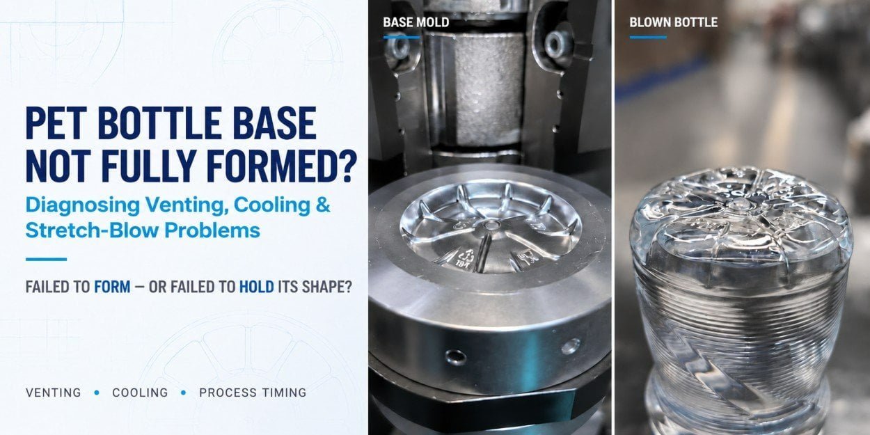
How Can You Tell a Base-Position Problem From a Cooling Problem?
A base-position problem normally creates a repeatable geometric difference tied to the same cavity, while a cooling problem often changes how well the base retains its shape after forming. Comparing bottle geometry immediately after molding, local base temperature, production speed, and cavity behavior can help separate the two.
Suppose cavity #6 consistently produces a push-up that is shallower than the other nine cavities.
One possibility is that the effective base-forming position is different.
But another possibility is that the PET initially forms correctly and then relaxes because the #6 base region is running hotter.
If local cooling flow is restricted, that cavity may not remove heat as efficiently as the others.
The bottle can look close to normal while constrained in the mold but lose definition after release.
This is why bottle appearance should be combined with process evidence.
| Observation | More Likely Direction |
|---|---|
| Base depth is repeatably different immediately after molding | Local forming position or geometry |
| Base looks acceptable at release but changes during cooling | Local cooling |
| Defect becomes worse as machine speed increases | Cooling capacity or effective cooling time |
| Local base temperature is consistently higher | Cooling circuit |
| Effective base position differs when measured from common datum | Assembly / tooling position |
| Changing or correcting the local base component changes the geometry immediately | Tooling condition |
Cooling problems can also be highly cavity-specific.
A multi-cavity mold may share the main cooling supply while still having local flow paths, channels, interfaces, restrictions, or connection differences.
Therefore:
one bad cavity does not automatically mean one bad base height.
The cavity pattern tells us where to look. The exact defect behavior tells us what condition within that cavity deserves attention.
How Can You Tell a Base-Position Problem From a Venting Problem?
Venting problems usually affect how completely PET reaches specific local details, while base-position differences change the fundamental location of the forming surface. A fixed shallow groove or incomplete foot therefore points in a different direction from a complete base whose overall depth is consistently shifted.
Suppose cavity #6 has the same general base depth as the other bottles, but one deep groove is always less defined.
That is not the classic pattern of a simple axial-position difference.
Air may be trapped in that local region.
A vent hole may be partially blocked.
A local vent path may not be functioning as intended.
Alternatively, the material distribution into that particular feature may be poor.
By contrast, if the entire push-up geometry of #6 appears systematically displaced relative to the other nine bottles, the assembled forming position becomes more important.
This difference is why troubleshooting should be based on the actual bottle result rather than on a general statement such as:
“Bottle-bottom problem means base-mold problem.”
We recently discussed this broader diagnostic logic in our article about incomplete base formation, where the main question is whether the bottle needs better venting, better cooling, different material distribution, or a change in the forming process.
For a fixed single-cavity inconsistency, the key additional question is:
Why does this one cavity respond differently when the shared process is the same?
Why Should You Compare Neighboring Cavities?
Neighboring cavities provide a useful reference because they operate in the same mold, under the same machine cycle, and normally experience very similar shared process conditions. Comparing cavity #6 directly with #5 and #7 can therefore reveal local dimensional, assembly, cooling, or venting differences more efficiently.
When one cavity differs, it is tempting to compare it only with the drawing.
The design drawing is essential, but neighboring production cavities offer another powerful reference.
Cavity #5 is already producing an acceptable bottle.
Cavity #7 is also producing an acceptable bottle.
That means the actual production system is showing us two working examples directly beside the abnormal position.
The comparison can begin with the finished bottles.
Are the base depths the same?
Are the gate positions similar?
Is the standing ring at the same level?
Does the heel transition match?
Is the brimful capacity consistent?
The comparison then moves to the mold.
Are the effective base-forming positions the same relative to a common reference?
Are the seating surfaces in comparable condition?
Is the center relationship consistent?
Are the venting features open?
Does the local cooling behave similarly?
This approach often reveals differences faster than evaluating the abnormal cavity without a reference.
How Should a 10-Cavity Linear Blow Mold Be Checked for Cavity-to-Cavity Consistency?
The most reliable method is to preserve cavity identity through several consecutive production cycles, measure the bottles systematically, and then compare the corresponding mold geometry from a shared reference. This separates repeatable cavity-specific differences from random production variation.
The first requirement is simple but important:
do not mix the bottles.
Every sample should retain its cavity number.
One production cycle gives useful information, but several consecutive cycles are better because they show repeatability.
If #6 is different once, the result may be accidental.
If #6 shows the same difference across repeated samples while the other nine remain stable, the evidence becomes much stronger.
A practical inspection record can look like this:
| Cavity | Base Depth | Gate Position | Standing Surface | Bottle Height | Brimful / Overflow Volume | Result |
|---|---|---|---|---|---|---|
| #1 | Reference range | Normal | Normal | Normal | Normal | Pass |
| #2 | Reference range | Normal | Normal | Normal | Normal | Pass |
| #3 | Reference range | Normal | Normal | Normal | Normal | Pass |
| #4 | Reference range | Normal | Normal | Normal | Normal | Pass |
| #5 | Reference range | Normal | Normal | Normal | Normal | Pass |
| #6 | Different | Check | Different | Check | Check | Investigate |
| #7 | Reference range | Normal | Normal | Normal | Normal | Pass |
| #8 | Reference range | Normal | Normal | Normal | Normal | Pass |
| #9 | Reference range | Normal | Normal | Normal | Normal | Pass |
| #10 | Reference range | Normal | Normal | Normal | Normal | Pass |
The actual acceptance limits should come from the bottle drawing, customer requirement, filling application, and mold specification. They should not be invented after the defect appears.
Once the bottle data confirms a cavity-specific pattern, the mold inspection should use a consistent mechanical datum.
Depending on the tooling and available inspection equipment, this can involve suitable height-measuring equipment, dedicated fixtures, dial indicators, or coordinate measurement.
The important point is not which instrument looks most sophisticated.
The important point is that all ten cavities are compared from the same meaningful reference.
The objective is:
not to prove that one loose part is different, but to determine whether one assembled cavity presents a different forming geometry to the PET bottle.
Why Is Measuring Only the Loose Base Component Not Enough?
A loose-component measurement isolates the part from its actual operating condition. It can verify component dimensions, but it cannot prove that the installed forming surface is located correctly after the component contacts its real datum, locating features, fasteners, and surrounding mold structure.
This is the same reason an accurately machined blow mold can still fit a machine poorly if the interface conditions are wrong.
Tooling works through relationships.
The cavity half relates to the opposite cavity half.
The base relates to the bottle centerline.
The complete mold relates to the blow molding machine.
For buyers ordering replacement or custom tooling, this mechanical relationship is just as important as cavity surface quality. Our article on why a new custom blow mold may not fit the blowing machine discusses how machine interfaces, mounting dimensions, cavity pitch, and tooling structure must be controlled together.
The same principle exists inside the mold.
A base component can meet its individual drawing and still be assembled into an incorrect final position if the installation condition is wrong.
That is why multi-cavity inspection should include both:
component dimensional inspection and assembled functional inspection.
They answer different questions.
Can One Base Insert Difference Change Bottle Capacity?
Yes, because the bottle base forms part of the internal volume. If one cavity has a different effective base geometry, the resulting bottle can have a different brimful or overflow capacity. The size of that difference depends on the actual bottle-base area and geometry, so it should be measured rather than estimated from a universal formula.
This relationship is particularly important when the visual difference is small.
A buyer may look at ten bottles and decide that the bases are close enough.
The filling line may reveal the problem later.
If one cavity has a systematically different internal volume, the relationship between fill quantity, headspace, and visible fill level can also differ.
The magnitude depends on the geometry.
Moving a relatively broad base surface changes more volume than changing a very small local feature by the same axial distance.
Therefore, statements such as:
“0.1 mm always equals X ml”
are not reliable unless they are based on the actual cross-sectional geometry of that bottle.
When capacity matters, measure the real bottle or calculate from the bottle CAD.
PETMOLDER has previously analyzed a more pronounced example in 30ml Capacity Variance in Same-Batch PET Blow Molds: A CNC Manufacturing Analysis. The broader lesson is the same: small tooling differences can become production differences once they are transferred into the finished bottle.
Why Should You Avoid Changing Global Parameters to Fix One Bad Cavity?
If nine cavities are stable and one fixed cavity is abnormal, large changes to shared heating, pre-blow, final blow, or cycle conditions can disturb the nine good bottles without correcting the local cause. A cavity-specific defect should therefore trigger a local investigation before a global process change.
This is one of the most practical lessons in multi-cavity troubleshooting.
Assume cavities #1–#5 and #7–#10 are producing acceptable bottles.
That tells us something important.
The existing blowing recipe is already capable of producing the required bottle geometry in nine out of ten tooling positions.
This does not prove that the recipe is theoretically optimized.
But it does prove that the recipe is workable for the current bottle and preform combination.
Now imagine increasing the oven temperature because cavity #6 appears shallow.
All ten preforms receive the changed heating condition.
Cavity #6 may improve slightly.
But the other nine bottles may begin to show new wall-thickness changes or base-distribution differences.
The same risk exists with pre-blow timing.
The same risk exists with high-pressure blowing.
The same risk exists with cycle changes.
A local tooling defect can therefore create a misleading process-tuning loop:
6 is different → change the global recipe → #6 changes slightly → nine normal cavities also move → adjust again → process window becomes narrower.
This is not efficient troubleshooting.
A better rule is:
Local defect → local investigation first.
Or more practically:
Do not move nine good cavities away from their process window to compensate for one local tooling problem.
Global process changes become more reasonable when several or all cavities show the same direction of defect, or when the local mold inspection shows no meaningful difference.
When Can a Global Process Change Still Be Relevant to One Sensitive Cavity?
A local cavity can expose a shared process weakness before the others do, especially if its cooling, venting, or geometry has less process margin. Therefore, “one bad cavity” should prioritize local inspection, but it should not permanently exclude process analysis if the local tooling proves correct.
This is an important limitation to the previous rule.
Troubleshooting should not become dogmatic.
Suppose cavity #6 has a slightly more restricted local cooling path than the others but still meets the mold design.
At moderate machine speed, all ten bottles are acceptable.
As production speed increases, #6 becomes the first cavity to show base deformation.
The immediate symptom is cavity-specific.
The underlying production limit may involve both local cooling margin and the global cycle.
Another example is venting.
If #6 contains the most difficult local air path because of a small but acceptable manufacturing difference, reducing high-blow pressure may cause #6 to lose definition first.
Again, the first inspection should still be local because #6 is the unique symptom location.
But after verifying the tooling, the process window may also need evaluation.
The correct principle is therefore not:
“Never change the process when only one cavity is bad.”
It is:
“Do not begin by changing a shared process until you understand why the defect follows one local cavity.”
That distinction leads to much cleaner troubleshooting.
How Can Local Cooling Create a Cavity-to-Cavity Difference?
Even when all cavities share the same cooling-water supply, local channels and interfaces may not transfer heat equally. A partially restricted passage, different flow condition, contamination, or contact issue can make one base run warmer and produce a different bottle-bottom geometry.
Cooling problems are particularly important around bottle bases.
The base often contains thicker local material than much of the sidewall.
This means it can require more effective heat removal before the bottle is released.
If cavity #6 has weaker local cooling, the PET may reach the correct metal geometry during blowing but remain softer when the mold opens.
The finished base can then relax slightly.
This can produce a different base depth even when the metal forming surface is correctly positioned.
That is why the bottle should not be used as the only evidence for a base-height diagnosis.
Cooling needs to be checked independently.
The cooling-water line should be inspected for actual flow rather than simply confirming that water is connected.
Return temperature can provide additional information.
A local restriction can sometimes be found by comparing neighboring circuits.
If machine speed is reduced and only the #6 base improves significantly, that also strengthens the case for thermal investigation.
However, slower production should be used as a diagnostic test, not automatically accepted as the permanent solution.
The production mold still needs to perform at the required output.
How Can Local Venting Make One Cavity Look Different?
A blocked or less effective vent path can prevent one cavity from reproducing deep base details even when the other nine cavities form normally. This usually appears as incomplete local replication rather than a uniform axial shift of the entire base geometry.
During high-pressure blowing, air between the PET and the mold surface has to leave.
Deep valleys and local base details are often among the last areas reached by the expanding material.
If cavity #6 contains a restricted vent path at one of those locations, the PET may repeatedly stop short of complete mold contact.
The resulting defect can be highly repeatable and cavity-specific.
The best response is not automatically to add more holes.
Existing vent features should first be inspected and cleaned.
The defect location should be compared with the expected final-contact region.
If the same local feature remains shallow while the overall base depth matches the other cavities, venting becomes much more plausible than a simple base-position difference.
This is another example of why the shape of the defect matters.
A cavity number identifies the location of the problem. The bottle geometry identifies the type of problem.
How Can a Local Surface or Parting Condition Affect the Bottle Base?
A cavity-specific bottle-base difference can also come from local wear, damage, contamination, mismatch, or an abnormal contact condition around the base interface. These effects may not change the nominal base height but can still alter how the cavity closes or how PET contacts the tooling.
In production tooling, the mold is repeatedly opened, closed, heated, cooled, cleaned, and serviced.
Over time, the local condition can change.
A damaged contact surface may prevent correct seating.
Wear can change a locating condition.
Contamination can accumulate where it is not obvious during a quick visual inspection.
An assembly can appear fully installed while still sitting slightly differently from the intended datum.
This is why mold maintenance should preserve not only the polished bottle-forming surfaces but also the mechanical reference surfaces behind them.
A scratch on a non-forming datum may never appear directly on a bottle surface, yet it can still change the position of the part that forms the bottle.
How Should the Abnormal Cavity Be Repaired?
The repair objective is not to make the abnormal bottle “look close enough.” The objective is to restore the local tooling to the original design relationship shared by the other cavities, then confirm that the corrected cavity produces consistent bottles under the same process.
If inspection confirms an assembly problem, the correction should address the assembly problem.
The datum may need cleaning.
An unintended burr may need to be removed properly.
A damaged seating feature may need restoration.
The base component may need to be reinstalled according to the original design condition.
If the actual component dimension is wrong, the correction should be based on the drawing and measured geometry rather than visually modifying the part until the bottle looks similar.
Likewise, if the problem is lateral alignment, adjusting axial height alone will not solve it.
If the problem is cooling, machining the base surface is the wrong repair.
If the problem is venting, the air path should be corrected based on the real final-contact region.
The repair method must follow the verified root cause.
How Should the Corrected Cavity Be Re-Validated?
After repair, cavity #6 should be compared with the other nine cavities over repeated production cycles. One visually acceptable bottle is not sufficient. The purpose of re-validation is to prove that the cavity has returned to the same geometric and production behavior as the rest of the mold.
The same measurements used to identify the defect should be repeated after correction.
Base depth should be compared.
Gate position should be checked.
Standing geometry should be verified.
Bottle height should be measured if relevant.
Brimful or overflow capacity should be compared when capacity was part of the original symptom.
If base-wall distribution was abnormal, thickness comparison should be repeated.
Most importantly, the cavity number must remain traceable during validation.
A useful repair loop is:
| Stage | Purpose |
|---|---|
| Preserve cavity identification | Confirm which position creates each bottle |
| Measure repeated samples | Prove that the difference is systematic |
| Inspect local tooling from common datum | Find geometric or assembly differences |
| Correct the verified local cause | Restore design condition rather than compensating blindly |
| Reassemble and trial | Confirm the tooling functions correctly |
| Compare #6 with neighboring cavities | Verify cavity-to-cavity consistency |
| Run repeated cycles | Confirm stability rather than one successful sample |
| Recheck capacity and critical dimensions | Confirm that the repair did not create a new problem |
A corrected bottle should not only look similar from one viewing angle.
The relevant production characteristics should return to the acceptable cavity-to-cavity range.
What Should Buyers Ask a Mold Supplier About Multi-Cavity Consistency?
For a multi-cavity PET blow mold, buyers should evaluate how the supplier controls cavity-to-cavity dimensions after assembly, not only how accurately individual CNC parts are machined. Inspection strategy, datum control, assembly verification, cooling consistency, and trial-bottle comparison all influence the final production result.
A supplier can own accurate CNC machines and still need a robust assembly and inspection process.
Multi-cavity consistency is created through the complete manufacturing chain.
The bottle cavity geometry must be consistent.
The base-forming surfaces must be positioned correctly.
The cavity pitch and machine interface must be correct.
Cooling passages must function consistently.
The assembled mold must close and align correctly.
The final verification should then look at real bottle output.
This is especially important for 6-cavity, 8-cavity, 10-cavity, and other high-output linear machines because even a small cavity-specific difference repeats continuously during production.
A one-cavity problem in a 10-cavity mold is not only a quality issue.
It also represents a significant share of production output.
That is why cavity-to-cavity consistency should be part of mold acceptance rather than something the customer discovers after long-term production begins.
FAQ
Why Does Only One Cavity in a 10-Cavity PET Blow Mold Produce a Different Bottle Base?
If the difference repeatedly follows the same cavity, start with that cavity’s local conditions. The effective base-forming position, alignment, seating datum, cooling, venting, wear, and assembly condition can all differ locally even though the ten cavities share the same blowing process.
Can a Small Base-Position Difference Change PET Bottle Capacity?
Yes. The bottle base contributes to internal volume, so changing the effective base geometry can change brimful or overflow capacity. The actual amount depends on the specific base shape and cross-sectional area, so it should be measured or calculated from the bottle geometry rather than estimated with a universal conversion.
Can One Base Be Misaligned Even When the Other Nine Cavities Are Correct?
Yes. A single cavity can have a local installation, datum, component, or assembly problem. Base height and center alignment should be checked separately because one controls axial geometry while the other influences symmetry around the bottle centerline.
Should I Change Blow Pressure If Only One Cavity Has a Different Bottle Bottom?
Usually not as the first step. If the other nine cavities are already producing acceptable bottles with the same shared recipe, investigate the abnormal cavity first. Large global parameter changes can move nine good cavities away from their existing process window without correcting the local cause.
How Do I Verify Cavity-to-Cavity Consistency in a Linear PET Blow Mold?
Keep every bottle identified by cavity number and collect samples over several cycles. Compare base depth, gate position, standing surface, bottle height, capacity, and other critical dimensions. Then inspect the corresponding mold geometry from a common mechanical datum to determine whether the abnormal cavity is physically different.
Conclusion
A 10-cavity linear PET blow mold gives engineers a powerful troubleshooting advantage: every cycle produces several bottles under the same shared process conditions.
When nine cavities are stable and one fixed cavity is different, that pattern is valuable information.
It tells us not to begin by treating the entire machine as though all ten cavities have failed.
The first question should be:
What is different at this local cavity?
The answer may be the effective base-forming position.
It may be lateral alignment.
It may be an assembly datum that is not fully seated.
It may be local cooling.
It may be a restricted vent path.
It may be wear or another cavity-specific tooling condition.
Only after these local factors have been evaluated should a global process change become the primary troubleshooting direction.
The most important inspection principle is equally simple:
Measure the assembled forming position—not only the loose component.
A multi-cavity mold is successful when ten individually manufactured and assembled cavity systems behave as one consistent production tool.
That consistency must be demonstrated in the bottles themselves.
In a 10-cavity linear blow mold, consistency does not mean ten parts look similar on the workbench. It means all ten assembled cavities produce the same bottle under the same process.
If one cavity in your PET blow mold repeatedly produces a different bottle base, provide the machine model, cavity number, bottle and preform drawings, mold drawings if available, photos of bottles identified by cavity, base-depth measurements, gate position, bottle height, capacity results, and information about local cooling and venting. These data make it much easier to separate a process problem from a cavity-specific tooling condition before any mold modification is made.
Related PETMOLDER Articles
- 30ml Capacity Variance in Same-Batch PET Blow Molds: A CNC Manufacturing Analysis
- Bottom Gate Off-Center? A 6-Step Protocol to Fix PET Bottle Eccentricity
- PET Blow Mold Preventive Maintenance: A Complete Guide for Aluminum and Stainless Steel Tooling
- Custom Blow Molds: 4 Reasons Your New Mold Won’t Fit Your Blowing Machine
- Semi-Auto vs. Fully Auto PET Blow Molds and Mechanical Compatibility