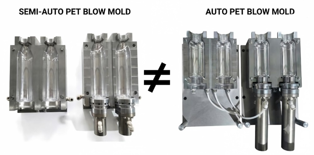
Transitioning from semi-automatic to fully automatic blow molding requires dedicated tooling. Semi-automatic molds lack the precise cavity center distances, synchronized bottom mold mechanics, and high-yield 7075 aluminum structures required to endure the high-pressure locking forces and continuous robotic transfer mechanisms of automated platforms.
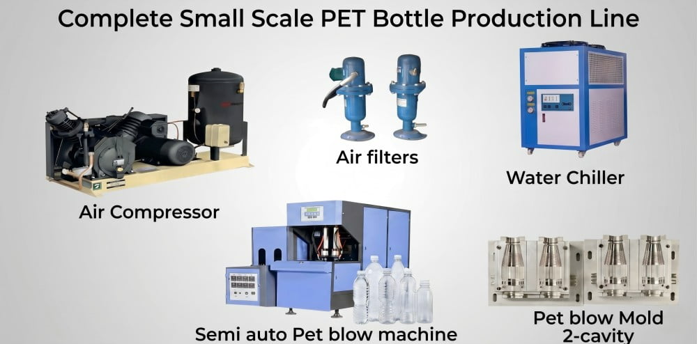
In my twenty years of managing PET mold and preform mold engineering operations at petmolder.com in Guangdong, China, I regularly review equipment upgrade blueprints submitted by overseas facility managers. A recurring operational challenge arises when facilities attempt to scale their output. Recently, a procurement director from a Vietnamese bottling facility submitted an inquiry. Experiencing a surge in order volume, his facility planned to integrate a new 2-cavity fully automatic blow molding machine. To minimize initial Capital Expenditure (CapEx), he inquired if his existing 2-cavity semi-automatic blow molds could be directly installed into the new automated platform.
I provided a definitive engineering response: they cannot be integrated.
He subsequently proposed an alternative: could we custom-build a fully automatic machine specifically engineered to accept his legacy semi-automatic molds? I advised that this is structurally unviable. In industrial manufacturing, attempting to merge incompatible kinematics and thermodynamics presents a significant engineering limitation. Many facility owners encounter this procurement scenario, assuming that matching cavity counts equate to structural interchangeability. Today, my engineering team and I will objectively analyze the mechanical, thermal, and metallurgical parameters that prevent semi-automatic tooling from functioning in fully automated environments, and why purpose-built tooling is necessary for production scaling.
1. What is PET Blow Mold Compatibility Between Semi-Auto and Fully Automated Platforms?
PET blow mold compatibility relies on precise mechanical kinematics rather than cavity count. Fully automatic platforms operate via servo-driven transfer systems requiring exact cavity center distances, whereas legacy semi-automatic tooling relies on manual preform loading with arbitrary center pitches, making direct interchangeability physically unviable.
The most frequent operational misunderstanding in facility upgrades is assuming that cavity count dictates compatibility. When procurement teams see a "2-cavity" specification on both their legacy equipment and their proposed automated machinery, they often assume the tooling is cross-compatible. This overlooks the fundamental kinematics of stretch blow molding.
A semi-automatic blow molding machine operates with a high tolerance for dimensional variance because it relies on human intervention. Operators manually extract heated preforms from the infrared oven and physically place them into the open mold cavities. Consequently, the distance between the two cavities (the center distance or cavity pitch) on a semi-automatic mold is arbitrary. It is designed primarily for operator ergonomics and basic platen spacing rather than mechanical precision.
Conversely, fully automatic blow molding machines—whether linear or continuous rotary platforms documented by major OEMs—eliminate manual loading entirely. They rely on microsecond-synchronized transfer arms, pitch chains, and star wheels to grasp the heated preforms and position them exactly into the mold carrier. The preform transfer pitch is mathematically fixed. If an automated machine's transfer center distance is engineered at 114.3 mm, the mold's cavity center distance must be machined precisely to 114.3 mm. Attempting to utilize a semi-automatic mold with an arbitrary center distance means the robotic arms will misalign, pushing the preforms against the mold face rather than inserting them into the cavities. For a foundational understanding of how these automated systems handle preforms, I advise reviewing what is PET two-stage molding and the factory process.
Semi-automatic configurations rely on manual preform loading, allowing for arbitrary cavity spacing that is incompatible with automated robotic transfer mechanisms.
| Kinematic Parameter | Semi-Automatic Platform | Fully Automatic Platform | Tooling Compatibility Implication |
|---|---|---|---|
| Preform Loading | Manual insertion by operator | Servo-driven robotic transfer | Automatic machines require exact geometric alignment. |
| Cavity Center Distance | Arbitrary (Ergonomic focus) | Fixed (Driven by transfer pitch) | Legacy molds will cause robotic transfer jams. |
| Operational Cycle | Variable (Operator dependent) | Continuous (Machine paced) | Automated cycles demand rigorous tooling tolerances. |
| Tolerance for Misalignment | High | Extremely Low | Misaligned cavities lead to severe machine faults. |
2. How to Evaluate Mechanical Interfaces: Mounting and Center Distance Mismatches
Evaluating mechanical interfaces involves analyzing the mold's mounting backplate and base mold synchronization. Automated machines demand precision locating pins, heavy-duty guide rails, and cam-actuated bottom molds to manage clamping forces. Semi-automatic molds utilize basic bolt configurations that yield under the intense kinetic impact of automated locks.
The physical barrier preventing tooling interchangeability extends beyond cavity pitch; it involves how the mold carrier absorbs kinetic energy. It is a significant engineering risk to assume that drilling new mounting holes into a legacy mold will render it functional for an automated platform.
Semi-automatic mold installation is mechanically straightforward. The tooling is typically secured to the machine's platen using standard bolts through a basic backplate. Because the clamping forces and operational frequencies on these manual machines are relatively low, the mold does not require complex alignment geometry.
Fully automatic machines operate under different physical parameters. To maintain an airtight seal against 35 to 40 bar of internal pneumatic blowing pressure during high-speed cycles, the machine's toggle or cam-actuated clamping system exerts tens to hundreds of tons of locking force. To manage this kinetic impact at sub-2-second cycle times, fully automatic molds require highly engineered Quick Mold Change (QMC) interfaces.
These automated molds feature precision-machined locating pins, heavy-duty alignment tracks, and specific backplate thicknesses designed to interface seamlessly with the machine's heavy platens. A semi-automatic mold lacks this structural integrity. If installed into an automated carrier, the intense clamping force will cause the mold to shift, leading to severe parting line dimension mismatch and asymmetrical containers. To understand the specific alignment parameters required for high-speed equipment, review our engineering guide on custom blow molds: 4 reasons your new mold won't fit your blowing machine.
Base Mold Kinematics: Fixed vs. Synchronized Structures
The most complex mechanical differentiation lies in the base mold (bottom mold) actuation. In semi-automatic equipment, the base mold typically relies on an independent pneumatic cylinder to rise and fall, or it may be a semi-fixed plate requiring the operator to manually leverage the bottle loose.
In fully automatic machines, extracting the container at high speeds without damaging the complex petaloid base requires exact mechanical synchronization. The base mold must retract simultaneously via precision cam linkages or servo-drives at the exact microsecond the lateral cavity halves open. Semi-automatic tooling lacks these specialized mechanical interfaces and slider tracks. Subjecting an independent, un-synchronized base mold to the rapid opening sequence of an automated carrier will result in the lateral cavities shearing the bottom geometry off the newly formed PET container.
3. Cost of Forced Tooling Modifications on High-Speed Lines
The financial impact of modifying semi-automatic molds for automated machines manifests as significant operational expenditure. Altering backplates compromises mold rigidity, causing uneven clamping stress that can fatigue the automated machine's tie bars and generate substantial production downtime, negating any initial capital savings.
Procurement teams must recognize that avoiding CapEx on new tooling by modifying legacy molds often leads to exponential Operational Expenditure (OpEx) through equipment fatigue. The practice of "forced modification" introduces severe mechanical liabilities to the production floor.
If a local machine shop attempts to adapt a semi-automatic mold by drilling new mounting holes, planing down the backplate to fit a QMC system, and retrofitting mismatched water hoses, the original structural integrity of the aluminum matrix is compromised. When this structurally asymmetrical "hybrid" mold is subjected to the continuous high-pressure clamping forces of an automated machine, the load distribution becomes uneven.
The consequences extend beyond producing defective bottles. Uneven clamping force transmits asymmetrical kinetic stress directly into the blow molding machine's frame. Over continuous cycles, this uneven load will bend the precision guide rails and can ultimately fatigue the machine's tie bars (the heavy steel columns that absorb the clamping force). Replacing a tie bar on a fully automatic machine requires dismantling major structural components, generating significant maintenance costs and halting production for extended periods. The initial savings of reusing an old mold are heavily outweighed by the resulting facility downtime. To evaluate the true costs associated with proper tooling fabrication, consult our comprehensive analysis on how much a PET blow mold costs.
| Modification Strategy | Upfront CapEx | Mechanical Consequence | Long-Term Operational Risk |
|---|---|---|---|
| Re-drilling Mounting Holes | Minimal | Compromises aluminum matrix rigidity | Mold shifting; severe parting line deviations. |
| Planing Backplates | Minimal | Alters compressive load distribution | Tie bar fatigue; machine frame misalignment. |
| Retrofitting Water Hoses | Minimal | Insufficient flow for high-speed cycles | Overheating; volumetric shrinkage of containers. |
| Procuring Dedicated Auto Molds | Standard Tooling Cost | Ensures engineered force distribution | Sustains machine lifespan and output (OEE). |
4. Common Problems of Using Suboptimal Molds in Automated Platforms
Integrating suboptimal tooling into automated platforms causes thermodynamic inefficiencies and severe container deviations. Semi-automatic molds lack conformal cooling channels required for high-speed thermal extraction and frequently exhibit parting line dimension mismatch under the high pneumatic pressure of automated manufacturing cycles.
Even if dimensional mounting parameters were theoretically resolved, the thermodynamic and internal mechanical structures of semi-automatic molds are incompatible with continuous high-speed production.
Thermal Dynamics and Heat Extraction
In stretch blow molding, the mold functions as a critical heat exchanger. The bi-axially oriented PET must be cooled below its glass transition temperature rapidly to freeze the molecular structure and prevent volumetric shrinkage.
Semi-automatic machines operate at lower Bottles Per Hour (BPH) rates, meaning the mold absorbs latent heat slowly. Consequently, their internal water channels are rudimentary—often just straight drilled passages utilizing standard hose clamps. Fully automatic machines process preforms rapidly, generating immense thermal loads. Automated molds require complex, multi-layered conformal cooling channels that map closely to the bottle's geometry. Furthermore, they utilize high-pressure, quick-release fluid connectors to manage massive water flow without leaking. A semi-automatic mold cannot extract heat fast enough for an automated cycle, resulting in deformed, overheated containers. If you observe containers losing volume overnight, analyze the thermal parameters outlined in PET bottle volume shrinkage analysis.
Parting Line Dimension Mismatch
In automated blow molding, ensuring a flush closure seam is critical. When a semi-automatic mold—which lacks hardened steel guide bushings and thick backing plates—is subjected to the 40-bar blowing air of an automated machine, the mold halves can be forced slightly apart. This creates a pronounced seam deviation (often referred to as parting line dimension mismatch) on the final container. This physical deviation compromises the vertical top-load strength required for palletizing.
Base Rollout and Deformation
Due to the lack of mechanical synchronization in the base mold actuation (as discussed in Section 2), the complex petaloid base of a carbonated soft drink container is highly susceptible to damage. If the base mold does not drop away cleanly at the exact moment of mold opening, the lateral cavities will drag across the newly formed feet. Additionally, if the semi-automatic base lacks high-grade steel reinforcements, the continuous pneumatic pressure will compress the aluminum, altering the transition radius and causing center gate bulging. For a deeper analysis of base issues, read our 6-step guide to fixing center gate bulging and rocker bottoms.
5. Semi-Auto Tooling Alloys vs. Fully Automated 7075 Aluminum Configurations
Fully automatic production demands metallurgical upgrades from standard aluminum to 7075 aviation-grade aluminum and S136 mold steel. Semi-automatic molds utilize softer alloys that yield under the continuous 40-bar pneumatic impact and mechanical clamping friction inherent to automated manufacturing environments.
Material fatigue dictates tooling lifespan. The metallurgical specifications that suffice for manual operations are inadequate for continuous automation.
Many semi-automatic mold manufacturers utilize standard, commercial-grade aluminum alloys to reduce raw material costs, as the mechanical clamping force and low operational frequencies do not induce significant kinetic stress. However, fully automatic machines subject the tooling to continuous mechanical stress. Operating multiple shifts per day, the mold experiences thousands of cycles per hour, absorbing up to 40 bar of internal pneumatic blowing pressure and immense external clamping force.
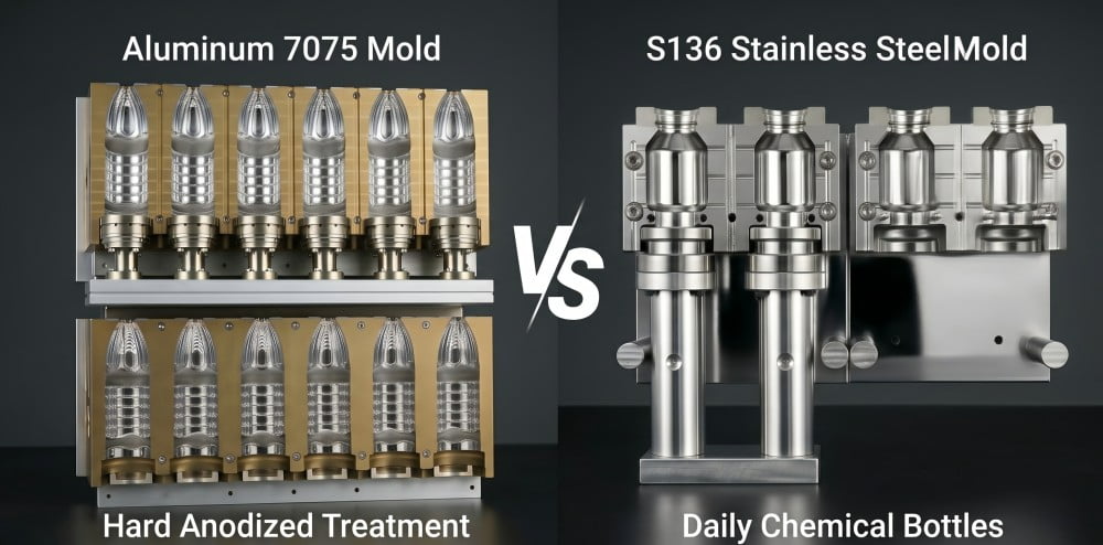
To prevent structural yielding, tier-1 mold manufacturers engineer fully automatic tooling utilizing premium alloys. The primary cavity blocks are CNC machined from 7075 or 6013 aviation-grade aluminum. This material offers superior yield strength while maintaining the high thermal diffusivity required for rapid cooling.
Crucially, the high-friction and high-impact zones—specifically the neck ring interfaces and the base mold inserts—cannot be constructed from aluminum. In automated molds, these critical zones are standardized with S136 premium mold steel (known for its toughness and corrosion resistance) and ultra-hard 7075 aluminum. If a legacy semi-automatic mold with unreinforced neck rings is placed into an automated machine, the clamping force will compress the soft aluminum over time, leading to preform misalignment and severe parting line deviations. For a deeper understanding of why composite metallurgy is the industrial standard, read why most PET blow molds are made of aluminum and steel inserts.
Fully automated platforms necessitate composite mold architectures, utilizing aviation-grade aluminum for thermal extraction and S136 steel inserts to resist kinetic impact at the neck and base.
| Metallurgical Component | Semi-Automatic Molds | Fully Automatic Molds | Engineering Rationale for Automated Use |
|---|---|---|---|
| Main Cavity Body | Standard Aluminum | 7075 / 6013 Aviation Aluminum | High yield strength prevents cavity deformation under continuous clamping pressure. |
| Neck Ring Interface | Integrated Standard Aluminum | S136 Mold Steel / 7075 Inserts | Prevents material galling and maintains exact preform vertical alignment. |
| Base Mold Insert | Standard Aluminum | S136 Mold Steel / 7075 Inserts | Absorbs 40-bar pneumatic impact; mitigates center gate bulging. |
| Guide Bushings | Direct tapped holes | Hardened Steel Sleeves | Ensures flush parting lines without elongating guide holes over millions of cycles. |
6. Case Study: Evaluating a 2-Cavity Upgrade for a Vietnamese Bottling Facility
A Vietnamese facility attempted to integrate legacy 2-cavity semi-automatic molds into a new fully automated platform to minimize initial tooling costs. The resulting mechanical incompatibility, specifically mismatched cavity pitch and inadequate thermal extraction, necessitated the procurement of dedicated automated tooling to achieve targeted output.
During the previous fiscal quarter, I consulted with the aforementioned Vietnamese water bottling facility. The plant operated several legacy semi-automatic lines and sought to upgrade to a linear 2-cavity fully automatic machine to reduce labor dependency and increase throughput. The procurement director's initial directive was to reuse their inventory of ten semi-automatic mold sets to avoid the CapEx of purchasing new tooling.
When we reviewed the technical specifications, the kinematic mismatch was apparent. The robotic transfer arms of the new automated machine were engineered with a fixed cavity pitch of 120 mm. The legacy semi-automatic molds, designed for manual insertion, had arbitrary center distances ranging from 110 mm to 118 mm. If installed, the automated transfer arms would physically push the preforms against the mold face rather than inserting them into the cavities, triggering immediate machine safety faults.
Furthermore, the facility's engineering team inquired if a custom fully automatic machine could be built with adjustable transfer arms to accommodate the varying pitches of their old molds. We explained that designing a continuous-motion transfer system with variable pitch parameters introduces severe mechanical instability and maintenance liabilities, outweighing any savings from reusing old molds. Additionally, the legacy straight-line water channels could not extract latent heat fast enough during the automated machine's sub-3-second cycle, which would result in containers exhibiting severe volumetric shrinkage.
The facility owner recognized the engineering reality: automation requires compatible, precision-engineered endpoints. We subsequently manufactured a complete set of dedicated fully automatic molds for their platform. Utilizing 6013 aviation aluminum for rapid thermal diffusivity and S136 steel neck rings for mechanical longevity, the new tooling integrated seamlessly with their automated transfer pitch. The facility achieved their target throughput safely and efficiently. To understand how to audit a tooling manufacturer's capability to deliver such precision, review 5 ways to spot a trader vs a real factory when looking for a preform mould maker.
7. Frequently Asked Questions (FAQ)
Q1: Both my semi-auto and new fully-auto machines are 2-cavity. Why can't I use the same mold?
A: Cavity count does not equal mechanical compatibility. Fully automatic machines utilize precise robotic transfer mechanisms (star wheels or pitch chains) that require an exact, mathematically fixed cavity center distance. Semi-automatic molds, designed for manual preform loading, have arbitrary center distances, making it physically unviable for automated arms to load preforms into the cavities without colliding.
Q2: Can I just drill new mounting holes on my semi-auto mold to fit the fully automatic machine?
A: Do not attempt this modification. Beyond basic mounting holes, fully automatic machines require specific backplate thicknesses, precise locating pins, and heavy-duty Quick Mold Change (QMC) interfaces to evenly distribute high-pressure locking forces. A modified semi-auto mold lacks structural rigidity, risking uneven clamping that can fatigue the automated machine's expensive tie bars.
Q3: Are the cooling water channels different between the two types of molds?
A: Yes. Semi-automatic molds manage low output volumes and utilize simple, straight-through water channels with basic hose fittings. Fully automatic molds run at high continuous speeds, requiring complex, geometry-mapped conformal cooling channels and high-pressure quick-connect interfaces to extract massive latent heat rapidly and prevent bottle deformation.
Q4: How does the bottom mold structure differ between the two platforms?
A: A semi-automatic bottom mold typically relies on an independent, basic pneumatic cylinder for movement. In contrast, a fully automatic base mold features complex mechanical slider tracks and linkages designed to synchronize precisely with the rapid opening of the main lateral mold halves. This synchronization is necessary to prevent shearing the bottle's base during high-speed ejection.
Q5: What materials are standard for engineering fully automatic blow molds?
A: To endure continuous high-frequency impact and 40-bar blowing pressures, tier-1 manufacturers engineer the main cavity body utilizing 7075 or 6013 aviation-grade aluminum for optimal heat dissipation. Additionally, premium S136 mold steel or 7075 inserts are integrated into high-wear areas, specifically the neck rings and base mold interfaces, to prevent dimensional yielding.
Executive Summary: Mechanical Compatibility Matrix
| Engineering Parameter | Semi-Automatic Blow Molds | Fully Automatic Blow Molds | Feasibility for Cross-Platform Use |
|---|---|---|---|
| Cavity Center Distance | Arbitrary (Operator focused) | Fixed (Robotic transfer focused) | Incompatible: Preforms will miss cavities. |
| Mounting Interface | Basic bolt alignment | QMC, locating pins, heavy backplates | Incompatible: Cannot withstand automated clamping force. |
| Cooling Architecture | Simple linear channels | Conformal cooling, quick-connectors | Incompatible: Causes severe volumetric shrinkage at high speeds. |
| Base Mold Kinematics | Independent cylinder operation | Cam-actuated mechanical synchronization | Incompatible: Lateral molds will damage the base upon opening. |
| Tooling Metallurgy | Standard commercial aluminum | 7075/6013 Aluminum + S136 Steel Inserts | Incompatible: Legacy alloys will yield under continuous pressure. |
Recommended Further Reading on PET Tooling Engineering
To further optimize your facility's equipment upgrades and ensure strict mechanical compatibility across your production lines, I advise reviewing these technical whitepapers from our engineering library:
- Custom Blow Molds: 4 Reasons Your New Mold Won't Fit Your Blowing Machine
- Why Are Most PET Blow Molds Made of Aluminum? 4 Engineering Reasons Explained
- PET Bottle Base Rollout Analysis: A 6-Step Guide to Fixing Center Gate Bulging and Rocker Bottoms
- What is PET Two-Stage Molding? The Ultimate Beginner's Guide to the Factory Process
- Looking for a Preform Mould Maker in China? 5 Ways to Spot a Trader vs a Real Factory