Sourcing your initial PET blow mold directly from the machine manufacturer eliminates diagnostic deadlocks during commissioning. This setup establishes an empirical performance baseline during Factory Acceptance Testing before transitioning to direct aftermarket tooling experts.
In the multi-year cycle of setting up and optimizing cross-border beverage production lines, evaluating procurement channels for machinery and tooling is a critical financial phase. A recurring strategic decision faced by procurement directors is whether to split the initial purchase of the stretch blow molding machine from the primary mold set. While segregating these line items appears fiscally advantageous on capital expenditure spreadsheets, this approach introduces unverified mechanical, pneumatic, and thermal variables during the initial equipment startup.
Throughout my more than 20 years of experience in PET mold and preform mold manufacturing in Guangdong, China, our engineering team has analyzed numerous stalled facility launches. While independent tooling experts excel at maximizing long-term operational efficiency and lowering replacement costs, utilizing aftermarket custom blow molds for the very first equipment commissioning phase introduces significant diagnostic complexity. This technical whitepaper analyzes the mechanical protocols of Factory Acceptance Testing (FAT), details the true cost of operational downtime during split-sourcing disputes, and defines the precise engineering metrics that indicate the safe pivot point to transition your tooling strategy to a direct source factory.
1. What is the Commissioning Trap in Split Procurement?
The commissioning trap occurs when a packaging facility separates the initial procurement of a blow molding machine from its primary tooling set. This creates an unverified production environment where mechanical or pneumatic defects cannot be isolated, resulting in extended downtime and a total absence of an operational baseline.
In the beverage packaging sector, split procurement is a highly tempting financial strategy. Many plant managers view a continuous-motion rotary blow molding machine as standard mechanical equipment and the mold as merely a detachable accessory. The operational assumption is that sourcing each component from separate low-cost vendors maximizes the short-term Return on Investment (ROI).
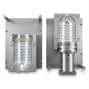
However, in stretch blow molding physics, the transition from an injection-molded preform to a bi-axially oriented container requires precise synchronization between the machine's infrared heating profile, the servo-driven stretch rod descent speed, and the high-pressure pneumatic blowing valves. The tooling functions as the physical vessel where these immense thermal and kinetic forces intersect.
When an untested custom mold is integrated into an uncommissioned blowing machine, the system lacks a control variable. If the resulting bottles exhibit material defects, the data is insufficient to pinpoint the cause. To understand the complex multi-stage thermodynamic timeline required to achieve physical container stability, engineers should study what is PET two-stage molding and the factory process. Until the equipment is calibrated using a verified baseline tool, introducing third-party geometric tolerances complicates the diagnostic environment.
2. How to Establish a Performance Baseline During Machine Commissioning
Establishing a performance baseline requires executing the initial Factory Acceptance Test utilizing the machine manufacturer's standardized mold. This process demonstrates that the equipment's core pneumatic proportional valves, mechanical clamping linkages, and cooling manifolds function at the specified hourly bottle capacity prior to introducing custom tooling configurations.
The primary objective of the initial mold set is not to deliver a highly optimized, ultra-lightweight new bottle shape. Its sole engineering mission is to serve as a standardized, stable calibration tool to verify machine performance metrics.
During the initial Factory Acceptance Test (FAT), the equipment manufacturer utilizes a proprietary, standard mold design with a known volumetric capacity, pre-calculated venting parameters, and verified cooling water circuit flow rates. By running this standard variable, the technicians can isolate and calibrate the machine’s internal operating mechanisms without geometric interference.
Critical Metrics to Verify During Initial Commissioning
- Pneumatic Stability: The high-pressure blowing valves must consistently deliver 35 to 40 bar air pressure without pressure drop deviations.
- Kinematic Alignment: The mechanical stretch rods must descend perpendicularly along the central axis of the cavity with a positioning repeatability within precise thresholds.
- Thermal Regulation: The infrared oven lamps must achieve stable heat penetration across the preform wall profile to prevent material crystallizing or stress whitening.
- Output Velocity: The complete mechanical system must run continuously at the contractual Bottles Per Hour (BPH) threshold without registering carrier locking errors.
Only when the blowing machine runs reliably with the manufacturer’s own reference mold can the line be certified as mechanically sound. For a structured look at auditing mold components during factory validations, consult the PET preform mold FAT checklist and inspection parameters. Once this mechanical baseline is securely recorded, the operational risk of integrating secondary, custom aftermarket tooling decreases significantly.
3. Cost of Machine Commissioning and Downtime Risks
The true cost of split procurement manifests as prolonged line stagnation, premium international courier fees for replacement inserts, and unrecoverable time-to-market delays. These operational expenditures rapidly exceed any initial capital savings achieved by sourcing the primary mold set from an independent third-party vendor.
Procurement teams frequently evaluate tooling proposals solely on upfront manufacturing quotes, omitting the potential financial compounding of an extended commissioning phase. When an initial startup fails due to split sourcing, the financial impact accumulates daily through idle factory floor overhead and lost retail placement.
For packaging facilities operating in regional export hubs like Africa or the Middle East, a technical dispute between separate machinery and tooling vendors introduces severe logistical friction. Time zone variations slow engineering communication. If diagnostic revisions require machining new cavity inserts or modifying pneumatic quick-release connectors, the facility must absorb expedited cross-border air freight costs and manage unexpected customs clearance delays.
Furthermore, delaying a product launch compromises the commercial timeline. In the fast-moving consumer goods (FMCG) market, an unrecovered 30-day delay can cause a brand to miss a seasonal summer hydration sales window entirely. To illustrate the long-term financial reality of tooling procurement, we analyze the structural variables across different manufacturing models below. For a comprehensive review of initial machining and metallurgical investments, see our comprehensive analysis on how much a PET blow mold costs.
| Operational Expense Item | Unified OEM Procurement (Machine + Reference Mold) | Split Sourcing Procurement (Unverified Third-Party Tooling) | Long-Term Financial Impact |
|---|---|---|---|
| Initial Capital Expenditure | Elevated due to OEM brand premiums | Optimized through direct direct factory quotes | Short-term asset conservation |
| Average Commissioning Duration | Typically 1 to 2 weeks to reach steady state | Often 4 to 8 weeks due to troubleshooting loops | Compounds labor and overhead costs |
| Component Replacement Logistics | Managed under a single unified factory warranty | Facility incurs cross-border freight and custom fees | Generates unplanned operational expenditure |
| Time-to-Market Execution | Aligned with seasonal launch schedules | Delayed by unresolved mechanical diagnostics | Causes forfeiture of peak regional sales revenue |
4. Common Problems of Split Sourcing for Initial Tooling
Common problems include parting line dimension mismatch, bottom gate off-center拉伸偏心, and localized material whitening. These structural defects occur when uncalibrated machinery parameters deform standard alloys, or when the lack of unified engineering accountability allows separate vendors to attribute mechanical failures to the opposing party's equipment.
The operational bottleneck typically begins when the untested machinery and the unverified third-party mold are first actuated together on the production floor. Under high-speed production stresses, physical non-conformances frequently emerge in the blown containers, initiating an accountability deadlock.
Parting Line Dimension Mismatch
In blow molding physics, we monitor parting line dimension mismatch or seam size deviations (the term "flash" is specific to injection molding parting lines and represents a conceptual inaccuracy in blowing terminology). If an independent custom mold is manufactured to nominal dimensions but the new machine's cam-actuated carrier locks exert uneven clamping force, the 40-bar blowing air will force the cavity halves slightly apart. This leaves a prominent, structurally weakened seam on the container that reduces the vertical top-load strength required for stable palletization. To prevent this, check the alignment parameters outlined in custom blow molds: 4 reasons your new mold won't fit your blowing machine.
Bottom Gate Off-Center (Stretching Misalignment)
A severe physical defect observed during uncalibrated startups is bottom gate off-center or stretching misalignment (note that true "gate eccentricity" occurs during preform injection molding; in the blow mold cavity, it manifests as a localized off-center material shift). If the machine's mechanical stretch rod path is slightly misaligned with the mold's central axis, the polymer is pushed away from the center gate area. This results in an asymmetrical base with thin, weak sections that yield under internal pressure.
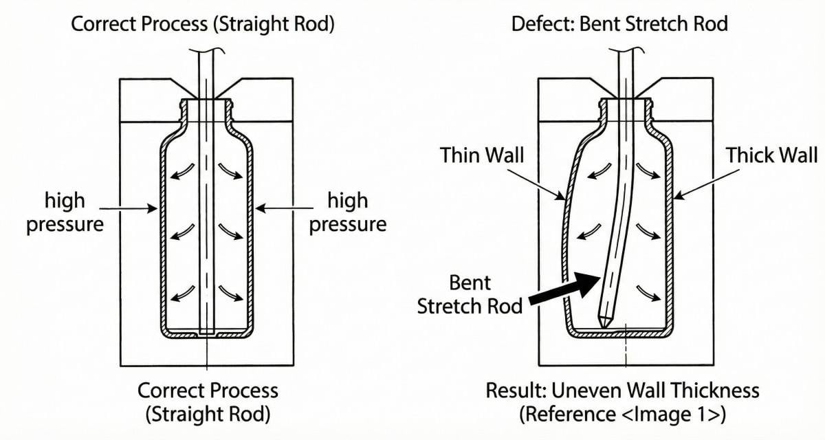
When this occurs during a split-sourcing launch, the machine vendor will claim the mold's neck ring interface is machined out of concentricity, while the tooling factory will argue the machine's stretch rod cylinder is bent. This prevents operators from executing the required 6-step protocol to fix PET bottle eccentricity and off-center gates.
Localized Polymer Whitening (Stress Over-Stretching)
If the machine's infrared oven settings fail to achieve adequate heat penetration through the preform wall, or if the pre-blow pressure valve timing is uncalibrated, the polymer undergoes cold stretching. This induces micro-tearing within the PET atomic matrix, resulting in localized haze or whitening on the container base or shoulder. Without a verified reference mold to isolate the heating performance, identifying whether the defect stems from the preform conditioning or the mold's base geometry is mathematically difficult. For full troubleshooting procedures once the machine is stabilized, study the 6-step guide to repairing localized whitening and pearlescence on PET bottles.
5. Machine Supplier Baseline Molds vs. Independent Custom Tooling
Machine supplier molds provide an essential reference variable for initial equipment sign-off but carry significant corporate premiums for secondary orders. Independent custom tooling factories deliver precise aftermarket replacement shells utilizing aviation aluminum and S136 stainless steel inserts, maximizing long-term facility ROI once production parameters stabilize.
Developing a highly profitable, scalable production facility requires identifying when to transition from machine supplier tooling to independent direct-source expert factories. The optimal pivot point occurs exclusively after the machine manufacturer has completed the FAT using their standard reference mold, and the high-speed machine is running steadily within your facility under steady-state thermodynamic conditions.
Once the equipment stability is empirically proven, the commercial reality of aftermarket procurement shifts. A substantial percentage of large blow molding machine OEMs do not operate extensive internal CNC mold machining centers for customized designs; they regularly outsource secondary custom bottle mold manufacturing to specialized third-party tooling factories. Consequently, ordering your second or third set of custom molds from the machine supplier often means paying a substantial administrative markup to a corporate middleman.
Equipment OEMs frequently structure their business models to sell the core blowing machinery at competitive margins to secure the initial facility contract, relying heavily on proprietary aftermarket components and secondary mold orders to generate high profits. When a facility plans to launch a new bottle design or expand capacity, the quote from the machine supplier often reflects this high-premium strategy.
This is the strategic inflection point to engage a direct-source tooling expert. Advanced manufacturing facilities engineer fully drop-in compatible shell molds engineered to interface seamlessly with existing Quick Mold Change (QMC) carrier systems used by major brands like Sidel or Krones. In our facility, we implement premium metallurgical specifications as standard features that OEMs often treat as premium upgrades.
We utilize 6013 aviation-grade aluminum for the primary cavity blocks to deliver excellent thermal diffusivity, allowing chilled water circuits to extract heat rapidly and minimize cycle times. For high-wear zones subjected to continuous mechanical clamping and pneumatic impact, we integrate S136 stainless steel and ultra-hard 7075 aluminum as standard base and neck ring inserts. This composite architecture prevents dimensional yielding and base rollout over millions of continuous production cycles, eliminating the premium vendor markups. To understand the physics behind this metallurgical configuration, review why most PET blow molds are made of aluminum and reinforced steel inserts.
| Engineering Specification | Machine Manufacturer Tooling (OEM Outsourced) | Tier-1 Direct Source Factory Molds | Operational & Mechanical Advantage |
|---|---|---|---|
| Pricing Allocation | High (Includes corporate overhead and multi-tier markups) | Optimized (Direct factory machine hours and raw material costs) | Increases facility capital efficiency for new product line rollouts. |
| Main Cavity Metallurgy | Standard Tooling Aluminum | 6013 Aviation-Grade Aluminum | Superior thermal diffusivity minimizes required polymer cooling cycles. |
| High-Stress Inserts | Standard alloy grades unless custom ordered | S136 Stainless Steel & 7075 Aluminum | High yield strength resists mechanical deformation under 40-bar pressure. |
| Quality Verification | Standard mechanical assembly checks | Micro-level Coordinate Measuring Machine (CMM) 3D scanning | Guarantees precise ±0.02 mm alignment with existing QMC carriers. |
6. Case Study: Resolving Initial Startup Delays with a Nigerian Facility
A Nigerian beverage facility experienced a multi-week commissioning delay when pairing an unverified high-speed rotary machine with third-party custom molds, resulting in severe pneumatic leaks and misaligned bases. The line achieved operational stabilization only after a standardized OEM reference mold was installed to isolate machine parameters and establish a baseline.
During the previous fiscal year, a mid-sized beverage producer in Nigeria established a high-speed municipal water bottling line to capture expanding regional market demand. To manage upfront asset costs, the facility's procurement team implemented a split-sourcing strategy: they acquired a brand-new high-speed continuous rotary blow molding machine from a prominent equipment builder, but awarded the contract for the initial set of customized petaloid PET blow molds to an independent regional tool shop.
The mechanical consequences became apparent immediately during the on-site startup phase. When the combined engineering teams initiated the continuous rotation sequence, the output consisted entirely of structurally non-conforming containers. The PET bottles displayed severe stress whitening across the base valleys (indicating uncalibrated pre-blow air timing or inadequate thermal penetration), off-center base stretching, and the machine's PLC recorded major high-pressure pneumatic leaks at the carrier nozzles.
The commissioning process stalled as both vendors presented conflicting root-cause analyses. The machine builder's technicians documented that the third-party mold’s external dimensions deviated from the carrier's required ±0.02 mm alignment tolerance, preventing a pneumatic seal, and asserted the internal micro-venting was insufficient to evacuate air during radial expansion. Conversely, the tool shop's engineers produced metrology data arguing that the machine’s stretch rod cylinder was mechanically misaligned, causing the off-center stretching, and that the pre-blow proportional valves failed to provide stable pressure.
The facility owner was caught in an expensive diagnostic deadlock while accumulating significant floor overhead. The resolution required halting the custom mold trials completely. The machine builder was authorized to air-freight their own standardized reference mold to the Nigerian plant. By installing this verified baseline tool, the commissioning engineers isolated the equipment variables: they successfully aligned the mechanical stretch rod paths, calibrated the infrared oven lamps, and stabilized the proportional valves without geometric interference from custom tooling.
Once the machine achieved stable continuous output with the reference mold, the facility established its performance baseline. The engineering team could then systematically analyze the third-party custom molds against a verified machine, modifying the dimensions to achieve full line compatibility. This empirical case highlights the fundamental industrial rule: isolate your machinery variables before scaling your custom tooling designs. To understand the diagnostic protocols used to resolve base variations once your machinery is certified as stable, review our 6-step guide to fixing center gate bulging and rocker bottoms.
7. Frequently Asked Questions (FAQ)
Q1: Why do you recommend purchasing the very first mold directly from the blow molding machine manufacturer?
A: The first mold is an essential diagnostic control variable required to pass the Factory Acceptance Test (FAT). Utilizing a standardized tool from the machine builder proves that the equipment's pneumatic valves, mechanical linkages, and internal cooling circuits operate to engineering specification, eliminating accountability disputes between separate vendors if defects emerge.
Q2: Do all major blow molding machine brands manufacture custom molds internally?
A: No. Many machinery builders function primarily as equipment designers and assemblers, outsourcing the physical CNC machining of customized bottle molds to specialized third-party tooling factories. Purchasing your secondary or replacement mold sets directly from an advanced direct-source factory eliminates these administrative OEM markups.
Q3: Why is the OEM quote for my second set of custom molds significantly higher than the market rate?
A: Many machinery builders operate on a commercial model where the core blowing machine is sold at tight margins to secure the facility contract. Long-term profitability is driven by high-margin secondary custom molds and proprietary aftermarket components. Once your machine baseline is stabilized, sourcing from an independent tooling expert optimizes your return on investment.
Q4: Will a replacement shell mold from an independent manufacturer integrate safely with my existing machine?
A: Yes, provided the manufacturer utilizes multi-axis CNC machining and precise metrology checks. Professional direct-source mold factories engineer 100% drop-in compatible shell molds. The external alignment tracks, locking pins, and quick-release fluid connectors are machined to precise dimensional tolerances to match your existing Quick Mold Change (QMC) carrier blocks seamlessly.
Q5: What metallurgical configurations ensure an aftermarket mold can withstand high-speed production stresses?
A: High-performance replacement molds utilize a multi-alloy composite structure. We specify 6013 aviation-grade aluminum for the primary cavity bodies to ensure rapid thermal diffusivity. For high-stress zones experiencing continuous 40-bar pneumatic impact and mechanical wear, we integrate S136 stainless steel and 7075 aluminum inserts into the base plates and neck rings to maintain strict dimensional stability over millions of cycles.
Executive Summary: The Tooling Sourcing Strategy Timeline
| Facility Development Phase | Tooling Procurement Decision | Engineering Objective | Risk Assessment Protocol |
|---|---|---|---|
| 1. Equipment Setup & Initial Commissioning | Procure baseline reference tooling from the Blow Molding Machine Manufacturer. | Execute a clean Factory Acceptance Test (FAT); verify mechanical strokes and pneumatic stability. | High risk if split procurement is attempted; high probability of diagnostic deadlock between vendors. |
| 2. Production Steady-State Calibration | Operate the machine supplier's baseline mold continuously. | Reach contractual BPH targets; establish steady-state thermodynamic profiles for the line. | Low risk; machine parameters are empirically recorded and isolated from tooling variables. |
| 3. Capacity Expansion & New Bottle Design | Source customized replacement shell molds from a Tier-1 Direct-Sourcing Factory. | Eliminate OEM middlemen markups; implement premium 6013 aluminum and S136 steel configurations. | Minimized risk; machine performance is certified; technical focus shifts exclusively to tooling metrology. |
Recommended Related Technical Guides
To further optimize your facility's production efficiency and analyze component wear patterns, review these technical whitepapers from our engineering library:
- Custom Blow Molds: 4 Reasons Your New Mold Won't Fit Your Blowing Machine
- Why Are Most PET Blow Molds Made of Aluminum? 4 Engineering Reasons Explained
- PET Bottle Base Rollout Analysis: A 6-Step Guide to Fixing Center Gate Bulging and Rocker Bottoms
- Bottom Gate Off-Center: A 6-Step Protocol to Fix PET Bottle Eccentricity
- Looking for a Preform Mould Maker in China? 5 Ways to Spot a Trader vs a Real Factory