Translating an AI PET bottle design into custom blow molds requires a structural engineering review, precise 3D CAD modeling, and rapid prototyping. Bypassing these steps leads to severe parting line deviations and demolding failures. This guide outlines the industrial protocol for optimizing AI concepts into manufacturable, multi-cavity production tooling.
In my two decades of managing PET mold and preform mold manufacturing operations in Guangdong, China, I frequently evaluate conceptual blueprints submitted by overseas procurement directors. Recently, a distinct shift has occurred in industrial packaging: design teams heavily utilize artificial intelligence to generate initial bottle concepts. While these generated images provide striking visual aesthetics, they consistently ignore the fundamental laws of polymer physics and blow molding kinematics.
Transitioning a two-dimensional AI concept into a physical, manufacturable container demands rigorous engineering intervention. Procuring custom tooling based directly on unmodified visual renderings leads to severe production line disruptions. This technical whitepaper analyzes the mechanical constraints of AI-generated shapes and outlines the standardized industrial protocol—from 3D prototyping to single-cavity pilot molding—required to validate packaging designs prior to scaling up for mass production. For a comprehensive overview of the entire manufacturing sequence, I advise reviewing from concept to production: what are the 8 steps to custom PET bottle molds.
1. What is the Challenge of AI PET Bottle Design?
AI-generated packaging concepts prioritize visual aesthetics while omitting critical thermodynamic parameters. These designs frequently feature severe undercuts, negative draft angles, and sharp geometries that prevent mechanical demolding and cause uneven bi-axial stretching, resulting in structural failure during the inflation phase.
The primary mechanical limitation of artificial intelligence in packaging design is its inability to calculate fluid dynamics and physical kinematics. In stretch blow molding (SBM), the heated preform is inflated radially via high-pressure air (frequently 35 to 40 bar) against the internal cavity walls. Once the bi-axially oriented polymer crystallizes, the two halves of the mold carrier must separate horizontally to eject the container.
AI image generators frequently produce geometries with severe undercuts. An undercut is a structural indentation or protrusion that prevents the mold from opening along its primary axis. If a bottle features a negative draft angle, the rigid PET material functions as a mechanical lock inside the aluminum cavity. Forcing the mold carrier open will tear the container or severely damage the tooling hardware.
Furthermore, AI designs often incorporate absolute right angles and extreme sharp edges to maximize visual impact. In polymer thermodynamics, sharp corners act as stress concentrators. The PET material encounters significant resistance when attempting to stretch uniformly into severe angles, leading to localized thinning, pearlescence (stress whitening), and eventual container rupture during the downstream filling process. Understanding the physics behind these geometric limitations is critical; I strongly recommend reading launching a square PET bottle: why sharp corners are the biggest nightmare in blow molding.
2. How to Execute Blow Mold Engineering for AI Concepts
Translating AI concepts into manufacturable tooling requires an experienced design engineer to evaluate the image, draft a functional 3D CAD model, and recalculate transition radii. This human-led CAD process establishes necessary draft angles and uniform material distribution before any CNC programming occurs.
In my workshop, the engineering team operates as a technical translation unit. When an overseas client submits an AI-generated packaging concept, we do not bypass the structural review phase. Direct CNC machining from an unverified 2D image or a rudimentary AI-generated 3D mesh is a severe engineering hazard. Industrial machining requires precise, mathematically defined toolpaths.
The initial phase involves a seasoned mold designer evaluating the visual concept. The designer then utilizes industrial CAD software to draft a functional 3D solid model. During this modeling phase, the engineer establishes a minimum draft angle of 1 to 2 degrees across all vertical surfaces. This slight taper is an absolute requirement to facilitate smooth demolding without scuffing the container's external surface.
The subsequent phase involves radius optimization. The engineer modifies the un-blowable sharp corners generated by the AI into smooth, calculated transition radii (R-angles). This mathematical adjustment allows the heated polymer to flow evenly during the high-pressure inflation phase, ensuring a uniform wall thickness distribution. Once the 3D CAD model is structurally optimized and approved by the client, the data is exported to CAM software to program the multi-axis CNC milling centers.
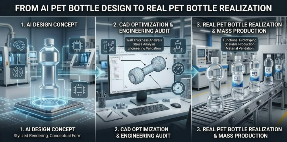
Engineering blueprint illustrating draft angle adjustments and transition radii required to adapt an irregular design for CNC machining.
Finally, we correlate the optimized geometry with a specific preform weight and neck finish. The overall stretch ratio dictates the container's final top-load strength. We calculate the preform dimensions required to distribute sufficient polymer mass into the specific contours of the design. To comprehend the complexities of adapting unusual geometries, review our guidelines on custom PET bottle molds and solutions for unique shapes.
| Engineering Phase | Input Data | Engineering Action | Output Deliverable |
|---|---|---|---|
| Concept Evaluation | AI-generated 2D image | Analyze undercuts and demolding feasibility | Technical feasibility report |
| 3D CAD Modeling | Verified visual concept | Draft solid model, apply 1-2° draft angles | Manufacturable 3D CAD file |
| Radius Optimization | Initial CAD draft | Recalculate sharp corners into smooth R-angles | Optimized surface topology |
| CAM Programming | Approved 3D CAD | Calculate spindle speeds and toolpaths | CNC machine instructions |
3. Cost of Rapid Prototyping vs. Direct Tooling Fabrication
Rapid 3D prototyping limits upfront capital expenditure by providing a rigid physical model within 24 hours for spatial verification. While cost-effective, these prototypes cannot simulate authentic polymer flexibility. Single-cavity pilot molds require higher investment but yield empirical physical data necessary for scaling.
Financial modeling for new product development requires mitigating risk before authorizing high capital expenditures for multi-cavity production molds. The standard protocol involves a tiered validation process.
The initial physical validation phase relies on rapid 3D prototyping. Utilizing industrial stereolithography (SLA) or Fused Deposition Modeling (FDM) printers, our facility produces a solid, three-dimensional representation of the engineered CAD model within 24 hours. The cost of this process is highly controlled. This physical model serves a specific, limited purpose: spatial verification. Procurement directors utilize this print to confirm the container's overall height, maximum diameter, and labeling area, ensuring it travels smoothly through existing conveyor star wheels without jamming.
However, the materials utilized in 3D printing (rigid resins or polylactic acid) possess fundamentally different mechanical properties than bi-axially oriented PET. The printed model features thick, rigid walls. It cannot provide accurate feedback regarding the container's ergonomics, flexibility, or squeeze resistance.
To acquire empirical physical data, facilities must invest in a single-cavity pilot mold (trial mold). This involves CNC machining a functional aluminum cavity. While the CapEx for a pilot mold is substantially higher than a 3D print, it represents a fraction of the cost of a full production set. The pilot mold produces genuine PET samples under standard thermodynamic conditions, enabling precise drop testing and top-load capacity evaluation. For a detailed breakdown of machining hours and material pricing, consult our comprehensive analysis on how much a PET blow mold costs.
4. Common Problems of Direct-to-Mold AI Designs
Bypassing the engineering translation phase for AI designs leads to parting line dimension mismatch, base rollout, and severe material thinning. Uncalculated geometries force the mold halves apart during high-pressure blowing, creating prominent seam deviations and structural instability in the final container.
Integrating unverified geometries into a stretch blow molding machine introduces significant mechanical risks. I frequently consult with overseas clients who experience severe line disruptions after attempting to mold experimental shapes without conducting proper kinematic analysis.
Parting Line Dimension Mismatch
A frequent deviation in suboptimal tooling is parting line dimension mismatch. In blow molding physics, we evaluate the closure seam; the term "flash" is specific to injection molding and is a conceptual inaccuracy here. If an AI design features complex lateral contours that place uneven pressure on the mold carrier, the high-pressure blowing air (up to 40 bar) forces the mold halves slightly apart. This creates a pronounced, weakened seam on the final container. The engineering solution requires analyzing the carrier interface and ensuring the design maintains symmetrical load distribution. For further insights into carrier compatibility, review 4 reasons your new mold won't fit your blowing machine.
Base Rollout and Deformation
Another severe mechanical deviation is base rollout, commonly referred to as center gate bulging. AI generators frequently design visually appealing flat bases that lack the structural petaloid or ribbed features required to withstand internal pneumatic pressure. During production, the unreinforced base yields under the continuous kinetic impact of the stretch rod and high-pressure air. The transition radius alters, creating a "rocker bottom" container that lacks stability on the filling conveyor. We detail the thermodynamic solutions to this specific deviation in our PET bottle base rollout analysis.
Localized Material Thinning
If the AI design features extreme stretch ratios—such as a very narrow neck expanding into a massive spherical body—the polymer will thin out dangerously at the maximum diameter. The PET material struggles to maintain uniform distribution across severe geometric transitions. This results in localized weak points that rupture during carbonation or high-speed filling procedures.
5. 3D Prototyping vs. Pilot Custom Blow Molds
3D prototyping provides rapid, cost-effective geometric validation for filling line compatibility but fails to replicate polymer bi-axial orientation. Pilot custom blow molds deliver authentic PET containers, providing the empirical thermodynamic and mechanical data required to authorize multi-cavity manufacturing investments.
Evaluating the transition from a digital file to a physical product requires understanding the distinct limitations of available prototyping methodologies.
3D Prototyping (SLA/FDM):
The primary advantage is velocity. Generating a physical representation of the AI-to-CAD translation within 24 hours accelerates the approval process. The output confirms aesthetic proportions and spatial footprint. However, the rigid layers of photopolymer resin cannot simulate the molecular alignment of stretched PET. Attempting to gauge the tactile consumer experience or structural integrity from a 3D print leads to inaccurate engineering assumptions.
Pilot Custom Blow Molds:
The pilot mold represents the definitive physical validation. A single-station CNC-machined cavity is installed into a testing machine and fed with the exact preform specified in the engineering plan. The resulting output is a genuine, bi-axially oriented PET container.
This process yields empirical data. Engineers can accurately assess the tactile squeeze feel, conduct destructive drop testing, and verify the transparency of the stretched polymer. Furthermore, pilot testing reveals thermal extraction bottlenecks; if a specific contour retains latent heat and exhibits post-mold volumetric shrinkage, the engineering team modifies the conformal cooling channels within the pilot cavity before fabricating the multi-cavity production set.
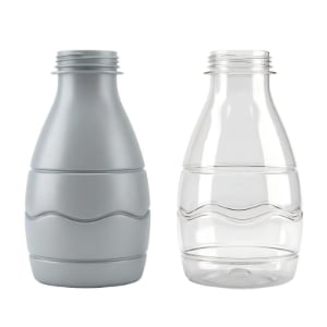
Physical comparison demonstrating the bi-axial orientation achieved via stretch blow molding, a physical property that 3D printing cannot simulate.
| Validation Protocol | Material | Core Function | Engineering Limitations |
|---|---|---|---|
| 3D Prototyping | Rigid Resin / PLA | Spatial verification; visual review | Cannot test elasticity, clarity, or drop impact. |
| Pilot Blow Mold | Bi-axially Oriented PET | Empirical physical & thermal testing | Higher initial cost; requires 2-3 weeks fabrication. |
| Production Mold | Aluminum & S136 Steel | Continuous high-speed output | Design is finalized; modifications are highly restrictive. |
6. Case Study: Engineering a Dumbbell-Shaped Functional Beverage Bottle
A Malaysian facility submitted an AI-generated dumbbell bottle concept featuring deep undercuts that prohibited demolding. By redrafting the 3D CAD model, optimizing the grip radii, and conducting pilot mold tests, our engineers delivered a blowable, structurally sound container optimized for continuous production.
During the previous fiscal quarter, I managed a complex engineering transition for a functional beverage brand based in Malaysia. The client submitted an AI-generated rendering of a bottle shaped like a dumbbell. The visual concept was highly effective for their sports nutrition branding. However, the AI had generated deep, hyper-realistic lateral indentations around the grip shaft and severe negative draft angles at the weighted ends.
If we had attempted to process this shape directly, the rigid PET would have locked instantly into the deep crevices of the grip section, rendering the mold carrier incapable of opening.
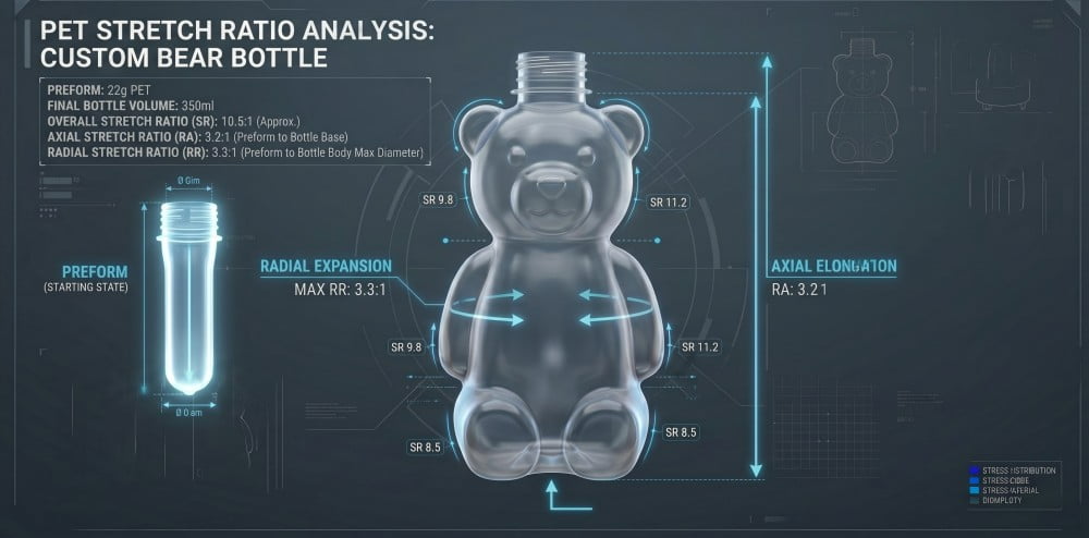
Our engineering intervention required a systematic modification of the topology. An experienced mold designer evaluated the image and drafted a new 3D CAD model. We smoothed the transition radii along the grip shaft and adjusted the lateral draft angles to a positive 2 degrees, ensuring smooth demolding while retaining the distinct dumbbell illusion. We calculated the axial stretch ratios to prevent the polymer from thinning excessively at the wide ends of the container.
We executed a 24-hour 3D print to allow the client's marketing team to verify the spatial dimensions. Upon approval, we CNC machined a single-cavity pilot mold. Initial pilot testing revealed slight pearlescence near the sharpest transitions due to cold stretching. We adjusted the infrared heating profile of the preform and optimized the pilot mold's internal cooling circuits to regulate thermal extraction. The resulting physical PET samples met all required top-load parameters, enabling the client to proceed to multi-cavity manufacturing safely. For guidance on troubleshooting similar visual defects, review our 6-step troubleshooting guide for PET bottle pearlescence and white haze.
7. Frequently Asked Questions (FAQ)
Q1: Can your CNC machines cut a blow mold directly from an AI-generated image?
A: No. CNC milling centers require precise mathematical toolpaths generated from 3D solid models. AI images are purely 2D conceptual renders. An experienced design engineer must first evaluate the image, calculate draft angles and material distribution, and manually draft a functional 3D CAD model before any CAM programming can occur.
Q2: What is the primary engineering value of a 3D printed bottle prototype?
A: The 3D printed model provides rapid spatial verification, typically within 24 hours. Because it utilizes rigid resin, it cannot simulate the elasticity or bi-axial orientation of PET. Its core value lies in confirming the container's height, diameter, and geometric proportions to ensure compatibility with your downstream conveyor and labeling equipment.
Q3: How do I accurately test the drop resistance and top-load strength of a new design?
A: To acquire empirical data regarding drop resistance, top-load strength, and ergonomics, we strongly advise utilizing our single-cavity Pilot Mold service. This protocol involves CNC machining a trial cavity to blow actual PET bottles under standard thermodynamic conditions, providing authentic samples for destructive testing.
Q4: How long does the transition from an AI concept to a physical pilot sample require?
A: Once the engineering team finalizes the 3D CAD model and your facility approves the design, we can generate a 3D printed prototype within 1 day. If you authorize a single-cavity Pilot Mold to evaluate authentic PET samples, the CNC fabrication and thermodynamic testing process generally requires two to three weeks.
Q5: What alloys are specified for multi-cavity production molds after the design is validated?
A: For high-speed production stability, we standardize a composite metallurgical architecture. We utilize 6013 aviation-grade aluminum for the primary cavity bodies to maximize thermal diffusivity. For high-stress zones experiencing continuous pneumatic impact, we insert S136 high-quality mold steel or 7075 aluminum into the base and neck rings to maintain strict dimensional tolerances. To understand this specification, read why most PET blow molds are made of aluminum.
Recommended Further Reading on PET Tooling Engineering
If your facility is evaluating conceptual packaging designs or analyzing production line deviations, I advise reviewing these technical resources from our engineering library:
- From Concept to Production: What Are the 8 Steps to Custom PET Bottle Molds?
- Launching a Square PET Bottle: Why Sharp Corners Are the Biggest Nightmare in Blow Molding
- Custom PET Bottle Molds: Solutions for Animal & Unique Shapes
- Custom Blow Molds: 4 Reasons Your New Mold Won't Fit Your Blowing Machine
- Looking for a Preform Mould Maker in China? 5 Ways to Spot a Trader vs a Real Factory
-1-300x300.jpg)