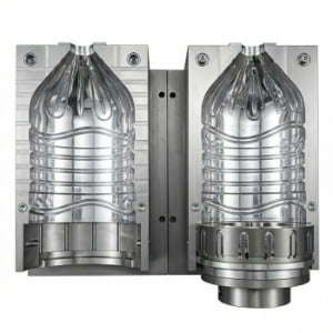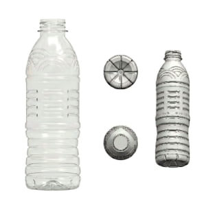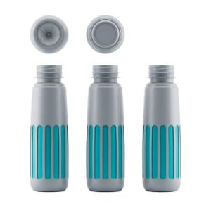
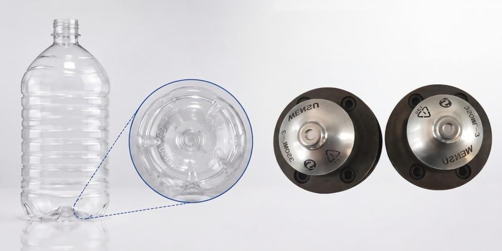
A PET blow mold bottom insert is a specialized, removable steel or aluminum module positioned at the base of a blow mold cavity that forms the concave push-up geometry and engraves essential traceability symbols—including cavity numbers, SPI recycling codes, production date stamps, and nominal volume metrics—onto the bottle base during high-pressure inflation.
I have spent 20 years managing PET mold manufacturing in Guangdong, China. During this time, I have frequently encountered overseas plant managers and quality engineers who tend to view the markings on the bottoms of PET bottles merely as aesthetic details. From a technical standpoint, however, these embossed characters actually represent a complex system of industrial coding.
Every alphanumeric character, recycling arrow, and alignment notch on a bottle base is created by precise, mirror-engraved features on the blow mold bottom insert. These markings serve as the foundational link for quality control (QC), regulatory compliance, and equipment maintenance in automated bottling plants. Understanding how bottom inserts are engineered, machined, and maintained is essential for optimizing line efficiency and establishing complete product traceability.
1. What is a PET Blow Mold Bottom Insert and Its Marking Function?
A PET blow mold bottom insert is a high-precision, interchangeable mold block designed to form the base push-up structure while engraving functional codes onto the bottle. These physical markings, including cavity numbers and SPI recycling codes, provide essential quality tracking and regulatory compliance for beverage packaging lines.
The bottom insert (often referred to as the base plug or bottom mold) operates as an independent component within the blow mold assembly. During the two-stage stretch blow molding process, the preform is axially stretched by a mechanical stretch rod and inflated radially by high-pressure air (typically 30 to 40 bar). The bottom insert supports the base push-up geometry, which is calculated to resist internal pressure and vertical stacking loads.
Simultaneously, the heated polymer is forced into the micro-cavities engraved on the insert surface. This mechanical contact embossses precise raised lettering on the container base. These markings are not decorative; they fulfill specific engineering and regulatory requirements:
- Cavity / Station Number: Identifies the exact mold position (e.g., Cavity 1 through 24) on linear or rotary blowing equipment, enabling instant isolation of mechanical deviations.
- SPI Recycling Code: Displays the universal resin identification symbol (a triangle of arrows enclosing the number "1" above "PET" or "PETE") mandated by global environmental standards.
- Date Indicator Insert: Incorporates an adjustable, rotating inner plug to physically stamp the month and year of production directly onto the bottle.
- Nominal Volume: Engraves the legally declared liquid capacity (e.g., 500ml, 2.0L) to satisfy international metrology laws.
- Food Contact Symbol: Features the stylized glass-and-fork icon to certify compliance with international food-grade packaging regulations.
- Brand Logo and OEM Identifiers: Embeds custom anti-counterfeiting trademarks and contract manufacturing tracking codes.
- Internal Engineering ID: Displays the mold drawing revision code (e.g., JD26-M04-B) to streamline spare parts reordering and maintenance records.
Understanding how base push-up geometry influences bottle stability is critical during the initial tooling phase, as detailed in our guide on preventing bottle stress cracking via base geometry.
| Marking Category | Primary Function | Regulatory or Operational Driver | Typical Location on Base |
|---|---|---|---|
| Cavity / Station Number | Quality tracking and equipment diagnostic anchor | Internal Quality Management (ISO 9001) | Perimeter ring or center push-up |
| SPI Resin Code ("1" PET) | Material identification for post-consumer recycling | Global Environmental Regulations (EU / FDA) | Center base area |
| Date Indicator Stamp | Batch-level manufacturing verification | Food Safety Traceability Protocols | Flat base panel |
| Nominal Volume | Legally declared fluid capacity verification | Weights and Measures Legal Standards | Outer base rim |
| Food Safety Icon | Material food-contact authorization proof | FDA / EFSA Packaging Directives | Base perimeter |
2. How to Engrave and Inspect PET Bottle Bottom Markings
Engraving PET bottle bottom markings requires precision micro-milling or laser engraving on bottom inserts, maintaining depth tolerances between 0.15mm and 0.30mm. Inspecting these markings involves Coordinate Measuring Machines (CMM) for mold steel and visual or vision-system verification of blown bottles during quality control audits.
Machining bottom inserts requires strict dimensional control. Because blow molding relies on physical contact between expanding plastic and cold mold steel, all text and symbols cut into the bottom insert must be mirror-engraved (reverse-engraved). If a character is cut normally into the metal, the blown bottle will display a reversed, unreadable symbol.
In our Guangdong machining center, we utilize two primary methods for bottom insert engraving:
- High-Speed CNC Micro-Milling: Utilizes carbide end mills with tip diameters down to 0.20 mm. Micro-milling produces smooth sidewall transitions with built-in draft angles (typically $15^\circ$ to $20^\circ$). This angle prevents the polymer from dragging against the steel during mold opening, which would otherwise cause visual scuffing or drag marks.
- Fiber Laser Engraving: Applied for intricate branding logos or small 2D matrix codes on hardened tool steels like S136. Laser engraving achieves high geometric accuracy without tool wear, though relief depth must be carefully controlled.
The depth of the engraved feature must be strictly maintained within 0.15 mm to 0.30 mm. If the engraving depth is shallower than 0.10 mm, the inflated PET material will not bridge the gap, resulting in faint, unreadable characters. Conversely, if the engraving depth exceeds 0.40 mm, the plastic will wedge deeply into the feature, inducing localized stress concentrations and causing ejection resistance that damages the bottle base.

Quality inspection occurs in two distinct phases. First, the machined bottom insert undergoes dimensional verification using a 3D Coordinate Measuring Machine (CMM) to confirm feature depth and alignment relative to the center gate. Second, during trial blowing, the physical containers are inspected under optical vision systems. Operators verify that cavity numbers correspond to line positions, allowing immediate troubleshooting if a specific station produces off-center base gates or volume deviations. For a complete audit protocol on multi-cavity tooling, consult our PET preform mold FAT inspection checklist.
3. Cost of PET Blow Mold Bottom Inserts and Custom Engraving
The cost of a PET blow mold bottom insert depends on material selection, cavity count, and engraving complexity, typically ranging from basic aluminum inserts to hardened S136 stainless steel modules with rotating date stamps. Investing in durable insert materials reduces long-term maintenance expenses and prevents frequent engraving degradation.
When evaluating the total cost of ownership for blow mold tooling, the bottom insert represents a critical component requiring balanced material selection. While the main cavity halves of a linear blow mold are frequently constructed from aerospace-grade aluminum to maximize thermal transfer, the bottom insert endures unique mechanical conditions.
During every blowing cycle, the mechanical stretch rod extends downward at high speed, striking the center gate area of the preform directly above the bottom insert. Furthermore, high-pressure air (30 to 40 bar) forces the thick amorphous plastic at the preform base against the bottom insert contours. If a low-tier aluminum alloy is selected for the bottom insert, this continuous dynamic impact will gradually deform the micro-engraved characters, causing cavity numbers and logos to blur after a few hundred thousand cycles.
In my workshop, we engineer bottom inserts utilizing two primary metallurgical specifications:
- Aerospace-Grade Al 7075-T6: Suitable for moderate-speed linear machines running non-abrasive products. Al 7075 provides excellent thermal conductivity (~130 W/m·K), assisting in rapid base cooling. However, it requires Type III Hard Anodizing (40-50 HRC) to protect micro-engravings from wear.
- Pre-Hardened or ESR-Grade S136 Stainless Steel: Hardened to 48-52 HRC, S136 stainless steel is the professional standard for high-speed rotary blowing lines and multi-cavity systems. S136 provides superior corrosion resistance against cooling water condensation and maintains razor-sharp engraving definition over millions of continuous production cycles.
Inserting rotating date stamps (Date Indicator Inserts) slightly increases initial tooling expenditure due to the precision-fit inner core required. However, these modular inserts allow operators to adjust the production month using a flathead screwdriver without removing the mold from the machine carriage, preventing hours of operational downtime. To analyze broader tooling capital expenditures, review our comprehensive breakdown on PET blow mold manufacturing costs.
| Bottom Insert Material | Surface Hardness | Thermal Conductivity | Engraving Longevity | Ideal Production Environment |
|---|---|---|---|---|
| Al 6061 (Standard Aluminum) | ~95 HB | ~160 W/m·K | Low (Prone to impact wear) | Short-run, low-speed prototype molds |
| Al 7075-T6 (Hard Anodized) | 40-50 HRC | ~130 W/m·K | Moderate (~1.5M cycles) | Medium-speed linear blowing equipment |
| S136 Stainless Steel (Hardened) | 48-52 HRC | ~20 W/m·K | Exceptional (5M+ cycles) | High-speed rotary lines; multi-cavity production |
4. Common Problems of PET Blow Mold Bottom Markings
Common problems with PET blow mold bottom markings include shallow text definition from insufficient blowing pressure, drag marks caused by excessive engraving depth, and off-center gate alignment. Managing these issues requires precise pneumatic pressure control, proper mold venting, and accurate stretch rod alignment.
In my interactions with overseas factory owners, I often troubleshoot base quality issues that trace back to bottom insert design or process parameter shifts. Because the bottle base contains the thickest polymer distribution, molding clean micro-characters requires precise thermodynamic balance.
Here are the primary technical deviations encountered in production:
- Faint or Unreadable Character Embossing:
- Root Cause: Insufficient high-pressure blowing air (HPB) or premature venting before the polymer fully fills the micro-grooves. Alternatively, the preform base temperature is too cool, increasing resin viscosity.
- Correction: Verify high-pressure blowing air reaches 35-40 bar. Ensure high-pressure timing extends long enough to lock the polymer against the steel before exhaust.
- Drag Marks and Base Scuffing (Ejection Resistance):
- Root Cause: Engraving depth exceeds 0.35 mm, or character walls lack sufficient draft angle ($<15^\circ$). As the mold opens or the bottom insert retracts, the plastic shears against the sharp steel edges.
- Correction: Re-machine the bottom insert to incorporate a $20^\circ$ draft angle and limit depth to 0.20 mm. Ensure bottom mold ejection timing is synchronized with cavity opening.
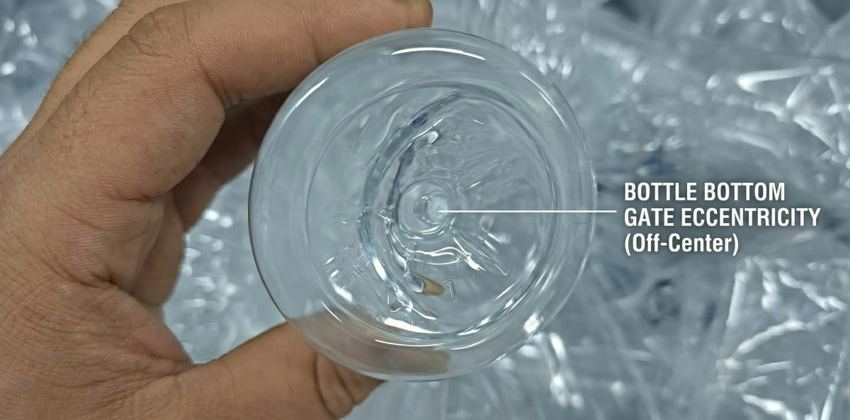
- Off-Center Markings Relative to Base Gate:
- Root Cause: Misalignment of the stretch rod or asymmetrical preform heating causes the preform center gate to shift laterally during stretching, obscuring the central SPI recycling code.
- Correction: Re-align the stretch rod axis and verify oven heating symmetry across all vertical zones.
- Trapped Air Blisters Over Engraved Features:
- Root Cause: Inadequate venting around the bottom insert perimeter. As PET inflates, air becomes trapped inside the deep recesses of the engraved characters, forming a pneumatic cushion that prevents full material contact.
- Correction: Machine micro-venting slots ($0.03\text{ mm}$ to $0.05\text{ mm}$ depth) behind the bottom insert mounting interface to allow rapid air evacuation.
If your line exhibits persistent base deformation or gate shift, follow our detailed 6-step troubleshooting protocol to fix PET bottle gate eccentricity.
| Base Defect Manifestation | Primary Mechanical / Process Cause | Engineering Corrective Action |
|---|---|---|
| Faint / Illegible Text | Low blowing pressure ($<30\text{ bar}$) or cold preform base | Increase HPB pressure; adjust lower oven lamp intensity |
| Base Drag Marks / Scuffing | Sharp engraving sidewalls ($<10^\circ$ draft angle) | Re-machine insert with $20^\circ$ draft angle; apply micro-polishing |
| Off-Center Base Markings | Mechanical stretch rod misalignment or heat imbalance | Align stretch rod stroke; balance radial heating profile |
| Blistered / Hazy Characters | Trapped air behind insert; localized moisture | Add $0.03\text{ mm}$ venting slots; check preform storage humidity |
5. Linear Machine Bottom Inserts vs. Rotary Machine Bottom Inserts
Linear machine bottom inserts are designed for multi-cavity block mounting with pneumatic or mechanical actuation, whereas rotary machine bottom inserts feature independent locking mechanisms and individual cooling circuits to withstand high-speed continuous carousel rotation and elevated mechanical impact forces.
The mechanical architecture of the blow molding machine dictates the physical design, mounting interface, and cooling configuration of the bottom insert. Understanding these distinctions is critical when ordering replacement tooling or upgrading production capacity.
In Linear Blow Molding Machines (operating intermittently at 1,000 to 8,000 BPH), bottom inserts are typically mounted onto a shared base bar or individual pneumatic lifting tables. The bottom inserts move vertically into position before the left and right cavity halves close around them.
- Cooling Setup: Linear inserts often utilize simplified water channels or rely on thermal conduction from the main mounting plate.
- Numbering Logic: Cavity numbers represent fixed positions along the linear mold frame (e.g., Cavities 1, 2, 3, 4).
In Rotary Blow Molding Machines (operating continuously at 10,000 to 80,000+ BPH on equipment from manufacturers like Krones or Sidel), every single molding station functions as an independent unit mounted on a rotating carousel.
- Cooling Setup: Each bottom insert features dedicated, high-flow cooling water channels integrated directly into the steel body. This design ensures rapid heat extraction from the thick base material, keeping cycle times extremely fast.
- Numbering Logic: The embossed number on the bottle base represents the specific Blow Station Number on the rotating carousel (e.g., Stations 1 through 24). If Station 14 produces a bottle with base deformation, the line operator can identify and isolate Station 14 without stopping the entire carousel.
To learn more about how machine layouts influence custom mold design and mounting interfaces, consult our guide on why custom molds fail to fit blowing machines.
| Technical Feature | Linear Machine Bottom Inserts | Rotary Machine Bottom Inserts |
|---|---|---|
| Kinematic Motion | Vertical actuation via shared pneumatic cylinder | Individual mechanical cam-driven jack mechanism |
| Cooling Channel Design | Simplified conduction or basic loop circuit | Internal high-flow conformal cooling channels |
| Material Requirement | Hardened Al 7075 or S136 Stainless Steel | Exclusively Hardened S136 Stainless Steel (48-52 HRC) |
| Numbering Designation | Static linear cavity position (e.g., Cavity 1 to 8) | Carousel station identification (e.g., Station 1 to 24) |
| Mechanical Load Profile | Intermittent vertical impact load | Continuous high-frequency impact and centrifugal force |
6. Case Study: Resolving Quality Tracking Failures in a 24-Station Rotary Line
A high-speed bottling facility experienced persistent base deformation and illegible tracking codes across a 24-station rotary blowing line. Replacing worn aluminum bottom inserts with hardened S136 stainless steel modules featuring micro-vented 0.20mm laser engravings restored code legibility and enabled instant cavity-level quality tracking.
Last year, an overseas beverage producer operating a 24-station high-speed rotary line contacted our engineering team. They faced a severe quality control bottleneck: the tracking codes and cavity numbers on their 1.5L CSD bottle bases were continuously blurring, making it impossible to pass retail optical verification audits. When quality deviations occurred downstream, QC technicians could not identify which rotary station produced the non-conforming containers.
Our technical audit revealed two underlying engineering flaws in their existing tooling:
- The bottom inserts were constructed from non-hardened aluminum. Over 18 months of continuous operation at 36,000 BPH, the high mechanical impact of the stretch rods had peened the aluminum steel, flattening the engraved numbers.
- The cavity venting behind the date indicator plugs was completely blocked by degraded lubricant, trapping high-pressure air that prevented the PET resin from contacting the character recesses.
We engineered a complete set of replacement bottom inserts manufactured from ESR-grade S136 stainless steel, vacuum-hardened to 50 HRC. We applied fiber laser engraving to cut all numbers and recycling symbols to a precise depth of $0.20\text{ mm}$ with a $20^\circ$ sidewall draft angle. Furthermore, we integrated internal high-flow cooling channels and added circumferential micro-venting slots ($0.04\text{ mm}$ depth) to ensure instantaneous air evacuation.
Upon installation, the results were immediate:
- The high-pressure blowing air pressed the polymer cleanly into the micro-engravings, producing sharp, highly legible characters across all 24 stations.
- Base cooling efficiency improved, resolving a minor base rollout issue and reducing overall cycle time by 0.3 seconds.
- The automated vision system achieved a 100% read rate on base cavity numbers, restoring full production line traceability.
For further insights into how thermodynamic optimization improves cycle performance, read our breakdown on how preform mold design impacts cycle time and energy consumption.
7. Frequently Asked Questions (FAQs)
Q1: Are all bottom markings mandatory on PET bottles?
No, regulatory requirements vary by region and application. The SPI recycling symbol ("1" PET), nominal volume, and food-contact icons are generally mandatory under international import laws and consumer protection standards. Conversely, cavity numbers, date indicator stamps, and internal factory engineering codes are voluntarily incorporated by manufacturers to enable internal quality control, preventive maintenance tracking, and brand protection.
Q2: What is the ideal engraving depth for bottom mold markings?
The industry standard engraving depth ranges strictly between $0.15\text{ mm}$ and $0.30\text{ mm}$, featuring a $15^\circ$ to $20^\circ$ sidewall draft angle. Engravings shallower than $0.10\text{ mm}$ produce faint, unreadable characters on blown bottles, while depths exceeding $0.40\text{ mm}$ cause plastic drag, base stress concentrations, and ejection resistance.
Q3: Why are the markings engraved in reverse (mirror image) on the bottom insert?
Blow molding is a direct replication process where hot plastic inflates outward against the cold cavity wall. To produce raised, correctly oriented, readable text on the final PET bottle exterior, all characters, numbers, and logos cut into the metal bottom insert must be machined in reverse (mirror image).
Q4: How do cavity numbers differ between linear and rotary blowing machines?
On linear blowing machines, the engraved number represents the static physical cavity position along the mold frame (e.g., Cavities 1 through 8). On rotary blowing machines, the number represents the specific, independent Blow Station Number on the rotating carousel (e.g., Stations 1 through 24), allowing line operators to isolate mechanical issues at a specific rotary module.
Q5: Can brand owners add custom anti-counterfeiting logos to the bottom insert?
Yes, custom brand logos, micro-lettering, and specific OEM tracking codes are widely utilized by major beverage brands. Using high-precision 5-axis CNC micro-milling or fiber laser engraving, intricate brand patterns can be cut into the bottom insert steel. This provides a low-cost, highly effective physical barrier against product counterfeiting and unauthorized grey-market distribution.
Summary Matrix: PET Blow Mold Bottom Insert Engineering Standards
| Metric / Parameter | Industry Standard Specification | Technical / Operational Justification |
|---|---|---|
| Material Selection | S136 Stainless Steel (48-52 HRC) or Hard Anodized Al 7075 | Resists stretch rod mechanical impact; prevents corrosion and wear |
| Engraving Depth | $0.15\text{ mm}$ to $0.30\text{ mm}$ | Guarantees clear visual definition without inducing base drag marks |
| Sidewall Draft Angle | $15^\circ$ to $20^\circ$ taper | Ensures clean mold release and eliminates plastic scuffing |
| Venting Clearance | $0.03\text{ mm}$ to $0.05\text{ mm}$ micro-slots | Prevents trapped air bladders over micro-engraved characters |
| Machining Technique | Mirror-engraved 5-axis CNC micro-milling or Laser | Replicates correct reading orientation on blown bottle base |
Conclusion: Engineering Control at the Base
In automated bottling operations, the bottle base is far more than a structural support; it is a digital and physical ledger of manufacturing quality. By specifying hardened materials like S136 stainless steel, maintaining strict $0.20\text{ mm}$ engraving depths with adequate draft angles, and implementing proper micro-venting behind bottom inserts, factory owners protect their lines from illegible codes, base stress failures, and untraceable quality deviations.
If you are designing a new PET bottle profile, upgrading bottom insert modules for existing molds, or experiencing persistent base quality issues, reach out to our engineering team at petmolder.com. We provide data-driven drawing evaluations and tooling solutions to ensure your production line operates with absolute dimensional precision and total traceability.
Related Technical Guides:
- PET Blow Mold Design Guide: Preventing Bottle Stress Cracking via Base Geometry
- PET Bottle Base Rollout Analysis: A 6-Step Guide to Fixing Center Gate Bulging
- Bottom Gate Off-Center? A 6-Step Protocol to Fix PET Bottle Eccentricity
- PET Preform Mold FAT Checklist: How to Inspect a 48-Cavity Mold Before Delivery
- Comprehensive Analysis: How Much Does a PET Blow Mold Cost?