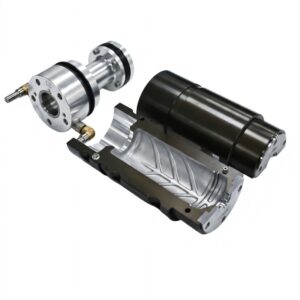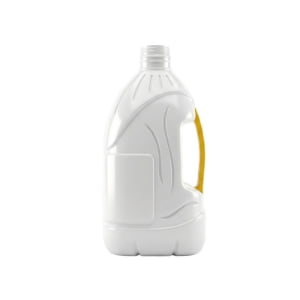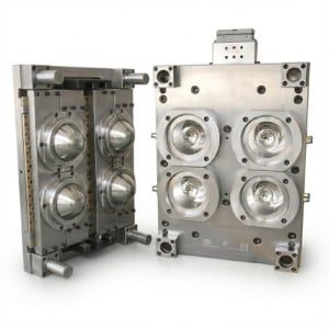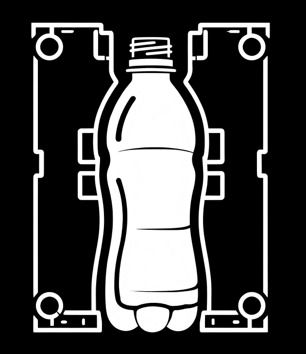
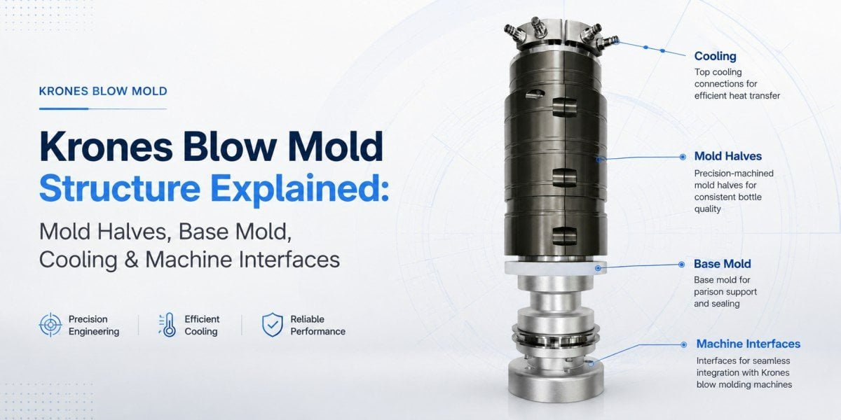
A Krones blow mold is not simply an aluminum block with a bottle cavity machined into it. On a high-speed rotary stretch blow molding machine, the forming surfaces, base mold, cooling system, venting, locating features, and machine interfaces all have to work together.
This becomes especially important when a bottling plant is developing a new bottle or sourcing replacement tooling for an existing Krones line.
The bottle cavity determines the shape of the finished container, but the mold-to-machine interface determines whether the tool can actually be installed, positioned, cooled, opened, closed, and operated correctly in the existing blowing station.
From our manufacturing experience, this distinction is where many replacement-mold projects become more complicated than buyers initially expect.
A bottle sample can tell us a great deal about the finished package. A machine nameplate can help identify the equipment. Neither one, by itself, necessarily defines every detail required to manufacture a replacement rotary mold.
The complete evaluation has to connect three things: the bottle that needs to be produced, the PET preform and blowing conditions used to produce it, and the physical interface of the machine already running in the factory.
What Are the Main Components of a Krones Blow Mold?
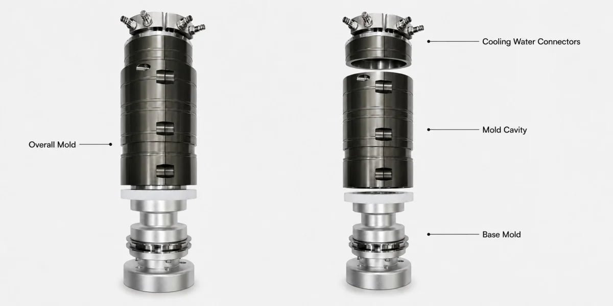
The principal forming components are the left mold half, right mold half, and base mold. A usable rotary mold also depends on cooling passages, venting, locating surfaces, mounting features, and other interfaces that connect the tooling with the blowing station.
It is helpful to distinguish between features that form the bottle and features that allow the mold to operate on the machine.
The two mold halves form most of the shoulder and bottle body. The base mold forms the bottom geometry. Cooling passages control heat transfer, while venting allows displaced air to leave the cavity as the PET expands.
The rear and external areas of the tool have another job. They must fit the existing machine correctly.
| Mold Area | Main Function | Why It Matters in Replacement Tooling |
|---|---|---|
| Left and right mold halves | Form the shoulder and main bottle body | Cavity geometry and closed-position alignment must remain consistent |
| Base mold | Forms the bottle bottom | Base shape, gate relationship and operating position affect bottle-bottom quality |
| Cooling system | Removes heat from the formed bottle | Internal passages and external connections must suit the production setup |
| Venting | Releases air displaced by the expanding PET | Influences reproduction of ribs, logos, recesses and base details |
| Mounting and locating features | Position the tooling in the blowing station | Incorrect references can prevent proper installation or alignment |
| Mold-side machine interfaces | Connect the mold package to the existing equipment | Must correspond to the actual machine configuration |
This is why we do not treat a replacement project as cavity copying alone.
Even if the bottle cavity is machined correctly, an error on the back side of the mold can still prevent the tool from running as intended.
Left and Right Mold Halves: The Main Bottle-Forming Components
The two mold halves create most of the external bottle geometry. In high-speed rotary production, their relationship to each other is as important as the accuracy of the individual cavity surfaces.
When the blowing station closes, the two halves meet along the bottle parting line and form the main cavity around the heated preform.
Depending on the bottle design, the cavity may contain a relatively simple cylindrical body or much more detailed geometry, such as shoulder transitions, label panels, reinforcement ribs, grips, recessed areas, logos, lettering, and decorative surfaces.
All of these features have to meet correctly when the mold closes.
A common mistake is to evaluate replacement tooling mainly from the quality of the visible CNC machining. Accurate machining is necessary, but it does not automatically guarantee correct assembly and repeated closing.
The cavity centerline, neck relationship, base position, parting surfaces, locating references, and mounting references must remain consistent as one system.
This becomes more noticeable when bottle details cross the parting line.
For example, if a horizontal rib continues from one mold half to the other, a small alignment difference may become visible on the finished bottle. The same applies to logos, decorative grooves, square bottle corners, or other features that rely on both sides of the cavity meeting at the intended position.
For PET stretch blow molding, the correct terminology is important.
A fine parting line mark may be a normal trace of the two mold halves meeting. A visible parting line mismatch or step at the parting line is different and should lead to an alignment investigation.
Possible causes are not limited to cavity machining. The condition may also involve the way the mold is positioned and supported in the machine.
On a high-speed rotary system, this relationship repeats continuously through production. The tooling therefore needs repeatable closed positioning, not merely correct dimensions during a static inspection.
Base Mold: Why the Bottle Bottom Uses a Separate Mold Component
The base mold is a separate forming component because the bottle bottom has its own geometry, cooling requirements, movement, and relationship with the side molds. It has a direct influence on bottle stability, gate position, base definition, and release from the cavity.
It should not be considered a simple bottom plate.
The base may contain a standing ring, push-up, reinforcement geometry, base feet, valleys, or a pressure-resistant petaloid structure depending on the bottle application.
For a still-water bottle, the design may focus on low material use, standing stability, top-load performance, and lightweighting.
For a carbonated beverage bottle, the base has to work under internal pressure. Its geometry and PET distribution therefore become part of the pressure-performance system rather than a cosmetic feature.
When a bottle is lightweighted, the base becomes even more sensitive to geometry because there is less excess PET available to compensate for an inefficient structure.
The relationship between the original preform gate and the bottle center also deserves attention.
If the gate appears noticeably off-center after blowing, the cause should not immediately be assigned to the base mold. Stretch rod alignment, preform centering, heating balance, material distribution, or mold alignment may also contribute.
Our article on PET bottle off-center gate and bottle eccentricity explains how these causes can be separated during troubleshooting.
Bottle-bottom problems can also appear after filling rather than immediately after blowing.
For example, a base may gradually become unstable and create a rocker-bottom condition. In that case, the investigation may involve base geometry, material distribution, filling conditions, thermal history, internal pressure, and cooling.
See our PET bottle base rollout and rocker-bottom analysis for a more detailed discussion.
Stress concentration is another reason the base should be evaluated carefully. The transition between the sidewall and bottom geometry can affect how mechanical and internal stresses are distributed through the bottle.
Our article on PET bottle stress cracking and base geometry covers this issue separately.
For replacement-tooling projects, the practical conclusion is simple:
The base mold should be reviewed as a functional forming component, not copied as an afterthought once the two side cavities are finished.
Cooling Channels and Water Connections in Krones Blow Molds
Cooling is part of the mold design, not an auxiliary detail. In continuous rotary production, the tooling must repeatedly remove heat from the newly formed bottle while maintaining stable cavity temperatures from one production cycle to the next.
The preform enters the blowing process in a heated condition so that the PET can stretch.
After the bottle expands against the cavity, heat transfers from the PET into the mold. The bottle must then reach sufficient dimensional stability for release and downstream handling.
This makes the mold both a forming tool and a heat-transfer component.
For a replacement project, two cooling questions have to be answered.
The first concerns the internal cooling layout. Channels need to provide useful heat transfer without interfering with cavity geometry, mounting features, fasteners, sealing surfaces, or the structural integrity of the tool.
The second concerns the external connection with the existing machine.
A cooling circuit can work perfectly inside the mold but still create an installation problem if the inlet, outlet, fitting orientation, sealing arrangement, or available clearance does not correspond to the plant’s actual equipment.
This is one reason photographs of the existing tooling can be valuable even when technical interface drawings are available.
A photograph may show the real hose direction, fittings, available space, or modifications that have been made during the service life of the machine.
For a high-speed rotary line, cooling consistency also matters across the complete set of blowing stations.
If thermal conditions vary significantly between stations, the plant may see differences in bottle dimensions, release behavior, or process stability even when the cavity shape is nominally the same.
Cooling therefore needs to be treated as part of the replacement-mold compatibility review, not as something to solve after installation.
Venting and Parting-Line Design for High-Speed Rotary Blow Molding
Venting gives the air inside the cavity a controlled path to escape as the PET expands toward the mold surface. Good venting becomes particularly important around fine ribs, deep recesses, logos, shoulder details, and bottle-base features.
Before the expanding bottle reaches the cavity wall, air occupies the space between the preform and the mold.
As the bottle forms, this air has to leave quickly enough for PET to reproduce the cavity details.
If air becomes trapped locally, features may appear less clearly defined. A rib may be shallow, lettering may lose definition, or a recessed feature may not reproduce consistently.
However, these symptoms should not automatically be diagnosed as venting defects.
Preform temperature, material distribution, pre-blow conditions, high-pressure blowing, and bottle geometry can create similar visual results.
The mold manufacturer therefore needs to look at the entire forming process rather than treating every incomplete detail as a ventilation problem.
Parting-line design has a similar relationship with high-speed operation.
The two mold halves must meet consistently while still providing the intended venting behavior. The objective is to release air without creating unnecessary visible marks on the bottle.
A small and consistent parting line is different from a geometric mismatch.
When the two sides of a rib, logo, or body surface do not meet correctly, the investigation should include mold alignment, locating condition, wear, contamination on closing surfaces, and the machine-side positioning of the tool.
This distinction is especially important when diagnosing a replacement mold. If the cavity is correct but the mold is not located correctly in the carrier, changing the cavity itself will not address the real problem.
Mold Mounting, Positioning and Locking Interfaces
For a replacement rotary blow mold, the machine-side interface is one of the most important parts of the engineering work. A supplier must reproduce not only the bottle cavity but also the physical relationships that allow the mold to fit and operate inside the existing blowing station.
This is where a general drawing labeled “Krones mold” becomes insufficient.
Krones has produced different machine platforms and equipment generations. Even within one brand, a mold should not be assumed to use a universal rear-side configuration.
The exact interface needs to be connected to the actual machine.
| Interface Area | What We Need to Understand | What Can Happen If It Is Wrong |
|---|---|---|
| Mounting surfaces | Where and how the mold is supported | Tool may not seat correctly |
| Locating references | How the mold reaches its intended position | Cavity, neck or base alignment may shift |
| Fastening and locking relationship | How the mold is retained during operation | Installation or closing can be affected |
| Base mold interface | How the base component is positioned and operated | Base may not align correctly with the side cavity |
| Cooling connection | How water is connected to the tooling | Installation, sealing or hose clearance problems may occur |
| Machine clearance | Space available around the installed mold | Connections or tool features may interfere with surrounding components |
Fasteners alone should not be treated as the precision reference for positioning.
The tool normally relies on defined reference and locating surfaces so that it returns to the required position after installation and during operation.
This positioning influences the relationship between the bottle centerline, neck, side cavity, and base mold.
The base component requires similar attention. Its machine-side relationship cannot be inferred from the finished bottle alone because the bottle does not reveal how the base mold is supported or moved.
Cooling also belongs in this interface discussion.
A tool may physically bolt into position but still be unsuitable for production if the water connections cannot be connected correctly.
This is why we use a simple rule in replacement projects:
Bottle geometry tells us what the mold must form. The machine interface tells us how the mold must operate.
For a broader explanation of machine-fit problems, see our guide to PET blow mold and blow molding machine compatibility.
Blow Mold vs. Mold Carrier: Which Parts Actually Belong to the Mold?
The blow mold is the removable tooling that directly forms the PET bottle. The mold carrier is part of the blow molding machine and supports, moves, closes, and positions that tooling during production.
The distinction may appear obvious to an equipment engineer, but it is not always clear during purchasing discussions.
In some factories, operators use the word “mold” for almost everything visible inside the blowing station. This can create confusion when quotations or replacement parts are being discussed.
The blow mold normally includes the two side-forming components, base mold, cavity surfaces, cooling passages, venting, and the mold-side features needed to connect the tooling to the machine.
The carrier remains part of the machine.
Its role is to support and operate the removable tooling through the repeated opening and closing process.
This distinction is commercially important.
If the customer only needs a new bottle mold, we should not assume that every component around the existing tool needs to be reproduced.
At the same time, the new tooling cannot be designed independently from the carrier.
The replacement mold has to match the interface already present on the machine.
This is also why measuring only the finished bottle solves only half of the problem.
A bottle tells us about the cavity.
It tells us almost nothing about how the back of the mold connects to the carrier.
Why Krones Machine Model and Generation Matter for Replacement Blow Molds
The statement “we have a Krones blowing machine” is not enough to release a replacement mold for manufacturing. The exact equipment and the configuration of the tooling already installed should be verified before the machine interface is finalized.
A brand name is not a dimensional specification.
Krones has developed different generations and configurations of its rotary stretch blow molding equipment. Machine-side arrangements can therefore differ depending on the specific platform and production configuration.
A nameplate is one of the first pieces of information we ask for because it helps identify the equipment correctly.
But it has a specific function.
The nameplate identifies the machine; it does not automatically confirm every dimension of the mold currently installed on it.
That difference is important, particularly when equipment has been in production for many years.
During its service life, a line may have received maintenance parts, upgrades, fittings, or other changes. Not every machine is modified, but a replacement-mold manufacturer should not assume that every historical drawing always represents the physical condition currently operating in the customer’s plant.
If an existing mold already runs successfully on the machine, that tool becomes a valuable physical reference.
We can compare its visible structure and selected dimensions against the interface information available for the machine.
Identification marks on the existing mold may also help when a factory operates several machines, bottle formats, or generations of equipment.
This additional verification is not intended to make the purchasing process more complicated.
It is intended to identify disagreements before material is machined.
Case Study: Why a Nameplate Was Not Enough for a Saudi 14-Cavity Krones Project
A real inquiry from a Saudi customer illustrates why machine identification and physical mold verification should be used together. The factory operated a 14-cavity high-speed Krones rotary blow molding machine and initially sent us the machine nameplate.
The customer knew that we maintain installation information for different blow molding machine brands, so he expected the nameplate to be sufficient for us to manufacture the new tooling.
His reasoning was understandable.
Once we identified the equipment, we were able to retrieve the corresponding machine-interface drawing available to us.
However, we did not immediately release the replacement mold for manufacturing.
We asked the customer to take clear photographs of the actual blow mold already running on the machine and to verify several dimensions against our reference drawing.
The purpose was not to redraw the complete machine.
We wanted to answer a much simpler question:
Does the reference information we have correspond to the physical tooling currently installed in this customer’s factory?
The existing mold allowed us to visually compare the overall construction, mounting arrangement, base component, cooling connections, and other visible interface features.
Where a dimension still required confirmation, the customer could check the actual tooling directly.
This created two independent references for the same project: our machine-interface data and the customer’s physical mold.
That is safer than relying on either one alone.
If an important mismatch is discovered before CNC machining begins, the drawing can still be corrected relatively easily.
If the same issue is discovered only after the mold has been completed and shipped to Saudi Arabia, the correction becomes much more disruptive to the project.
The key lesson from this case is not that a machine nameplate is insufficient or unimportant.
It is extremely useful.
The lesson is that machine identification should begin the compatibility check, not automatically end it.
For third-party high-speed rotary tooling, comparing available technical information against the actual installed mold is a practical way to reduce avoidable assumptions.
Why a Bottle Sample Alone Is Not Enough for a Replacement Mold
A finished PET bottle provides valuable cavity information, but it does not reveal the mounting, locating, cooling, or machine-side geometry on the back of the mold. A replacement tool therefore should not be defined from the bottle sample alone.
From a physical bottle, we can study the external profile, shoulder, base, ribs, parting line, logos, surface details, and many dimensional relationships.
Those are all useful for reproducing the cavity.
But the finished bottle cannot show how the existing mold is attached to the machine.
It does not reveal the rear locating surfaces, cooling fittings, carrier relationship, base-mold mechanism, or hidden internal passages.
This is the difference between reproducing bottle geometry and manufacturing a tool for a particular machine platform.
Both tasks are necessary in a replacement project.
If the supplier accurately reconstructs the bottle but guesses the machine interface, the tool may still need modification before production.
Our article Custom Blow Molds: 4 Reasons Your New Mold Won’t Fit Your Blowing Machine discusses this problem in more detail.
What Should You Check Before Ordering a Replacement Krones Blow Mold?
Before placing an order, the buyer and mold manufacturer should agree on the bottle to be produced, the preform to be used, the actual machine platform, the existing mold interface, the cooling arrangement, and the expected production conditions.
The objective is not to collect as many parameters as possible.
It is to identify the few project conditions that change the mold design.
For example, a direct replacement of an existing bottle may require less bottle-development work because the current mold and finished container already provide strong references.
A completely new bottle on the same machine is different. The machine interface may remain the same, but the cavity, base geometry, preform relationship, cooling demand, and bottle-forming behavior still need to be evaluated.
A used machine with incomplete tooling records creates another situation. In that case, physical inspection of the working mold becomes much more important.
The project should therefore be classified before the supplier starts requesting dimensions.
| Project Condition | Most Important Reference | Additional Verification Usually Needed |
|---|---|---|
| Direct copy of a currently running mold | Existing working tool | Confirm critical interface dimensions and bottle requirement |
| New bottle on an existing Krones machine | Verified machine interface | Bottle design, base geometry and preform suitability |
| Original drawing unavailable | Existing physical mold | Photographs and selected direct measurements |
| Used or older production line | Machine identification plus installed tooling | Check that reference data matches current hardware |
| Different filling application | New bottle requirement | Base design, material distribution and production conditions |
| Different preform | New preform drawing or sample | Stretch relationship and bottle-forming feasibility |
Material and surface requirements should also be confirmed before production.
Aluminum is commonly used for PET blow molds because it combines suitable machining characteristics with useful thermal conductivity and relatively low tool mass. However, the exact alloy and treatment should be chosen according to the tooling requirement rather than simply requesting “aluminum.”
For more detail, see Aluminum vs. Steel Blow Molds: How to Choose the Right Material.
Can a Replacement Mold Be Made Without the Original Krones Drawing?
Yes, a replacement project can still be evaluated when the original mold drawing is unavailable, but the manufacturer will normally need stronger physical references from the tooling and machine that are already in the factory.
This situation is not unusual.
A production line may have been operating for many years. Technical files may be stored in another department, the equipment may have been purchased used, or the original mold may have arrived as part of a complete line without a separate manufacturing drawing.
The absence of the original drawing does not automatically prevent a replacement project.
It changes the way the project is verified.
The first step is to identify the equipment as accurately as possible.
The next reference is the mold currently running on that equipment.
The supplier can then compare the actual tooling against available machine-interface information and determine which dimensions genuinely need to be checked.
If the replacement is also introducing a new bottle, the project has two separate engineering tasks.
The first is to preserve the verified machine interface.
The second is to develop the new bottle-forming cavity around the required bottle, preform, and production conditions.
This distinction is important because a new bottle does not require the manufacturer to rediscover the machine interface every time.
Once the correct interface has been verified, it becomes a controlled machine-side reference for the project.
What Information Should You Send to a Krones Blow Mold Manufacturer?
For an initial replacement-mold evaluation, it is better to send a small set of complete references than a long list of disconnected dimensions. A machine nameplate, existing tooling information, bottle definition, and preform data usually provide a much clearer starting point.
The information can be organized into five groups rather than sending dozens of individual parameters in separate messages.
| Information Group | Useful Reference | What It Allows Us to Evaluate |
|---|---|---|
| Machine | Clear nameplate photo and exact equipment identification | Determines which machine-interface reference should be checked |
| Existing tooling | Overall photos, rear/interface photos, base mold and available drawing | Shows the physical configuration currently running |
| Bottle | Drawing, 3D file or physical sample | Defines cavity shape and critical bottle geometry |
| Preform | Drawing or sample with neck and weight information | Helps evaluate stretch and material-distribution conditions |
| Production | Filling application and intended operating requirement | Provides context for base design, cooling and bottle performance |
If our reference data and the customer’s mold appear consistent, we do not need the customer to measure every feature on the tool.
We only ask for measurements where confirmation is actually necessary.
This is important for two reasons.
First, it reduces unnecessary work for the customer’s maintenance team.
Second, it reduces the chance of measurement errors created by asking someone to record dozens of dimensions that do not affect the replacement design.
Where the original mold drawing is available, it can significantly simplify the process.
Where it is not available, good photographs and targeted measurements can still provide useful verification.
Why Mold Material and Cooling Should Be Considered Together
A PET blow mold is both a forming tool and a thermal component, so material selection and cooling design should be evaluated together rather than as separate purchasing items.
An alloy may be easy to machine and strong enough for the application, but the tool must also repeatedly remove heat from the bottle during production.
For high-speed rotary equipment, this thermal role becomes particularly important because every blowing station operates continuously.
Cooling channel placement therefore has to balance heat transfer with the mechanical structure of the mold.
The manufacturer cannot simply move water passages closer to the cavity without considering mounting areas, screw positions, sealing regions, wall thickness, and other internal features.
Surface treatment is another application-dependent choice.
Two molds manufactured from the same nominal aluminum alloy may have different surface requirements depending on the bottle, factory conditions, cleaning method, and maintenance strategy.
This is why the material specification should be discussed in the context of the complete production environment.
For factories comparing common tooling materials, our aluminum versus steel PET blow mold guide provides a more detailed comparison.
FAQ
What are the main parts of a Krones blow mold?
The main forming components are the left mold half, right mold half, and base mold. The complete tool also includes cooling, venting, locating features, and machine-side interfaces required for installation and operation. For replacement tooling, those interface details are just as important as the visible bottle cavity.
Can a replacement blow mold be made for a Krones Contiform machine?
Yes. The key requirement is to verify the specific machine and existing tooling configuration before manufacturing. The replacement project should connect the required bottle geometry with the actual mounting, base, cooling, and positioning conditions of the machine rather than copying only the finished bottle.
Are all Krones blow molds interchangeable?
No. Krones has different equipment platforms and generations, so a mold should not be assumed to fit another machine simply because both machines carry the same brand. The actual interface and existing tooling should be checked before a replacement is approved.
What information is needed for a Krones replacement mold?
A practical starting package normally includes the machine nameplate, clear photographs or drawings of the current tooling, the bottle drawing or sample, and the preform information. The mold manufacturer can then identify which interface dimensions require direct verification rather than asking the customer to measure the complete tool.
What is the difference between a blow mold and a mold carrier?
The blow mold is the removable tooling that forms the bottle. The mold carrier belongs to the blowing machine and supports and operates that tooling. A replacement mold normally reuses the existing carrier, which means the new tool must match the carrier and other machine-side interfaces correctly.
Final Recommendation
When sourcing a Krones blow mold, do not judge compatibility only by whether the supplier can reproduce the bottle cavity. The more important question for replacement tooling is whether the finished mold matches the actual blowing station operating in your factory.
A machine nameplate is an excellent starting point because it identifies the equipment.
An existing mold provides a second reference because it shows how that equipment is physically configured today.
The bottle and preform then define what the new tooling must produce.
When these references agree, the replacement project becomes much more controlled.
When they do not agree, the difference should be resolved before CNC machining begins.
That is the approach we used with the Saudi customer operating a 14-cavity high-speed Krones rotary machine. We first identified the equipment from the nameplate, retrieved the corresponding interface information available to us, and then asked the customer to verify the real mold installed on the line.
The objective was not to create additional purchasing steps.
It was to avoid assuming that reference data and physical equipment were identical without checking.
If you are developing a new PET bottle or replacing tooling on an existing Krones line, you can send PETMOLDER the machine identification, existing mold reference, bottle information, and preform data first.
We can then determine which interface details actually require confirmation before the mold design is released for manufacturing.
Related PETMOLDER Articles
- High-Speed Rotary Blow Molds for Krones & Sidel: A Guide to Premium Compatible Tooling
- Semi-Auto vs. Fully Auto PET Blow Molds and Mechanical Compatibility
- Custom Blow Molds: 4 Reasons Your New Mold Won’t Fit Your Blowing Machine
- PET Blow Mold Preventive Maintenance: A Complete Guide for Aluminum and Stainless Steel Tooling
- Aluminum vs. Steel Blow Molds: How to Choose the Right Material