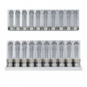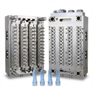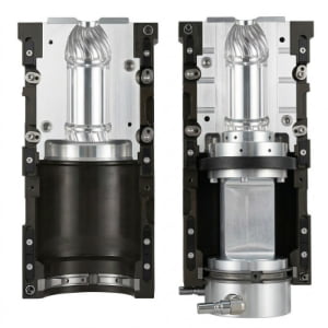
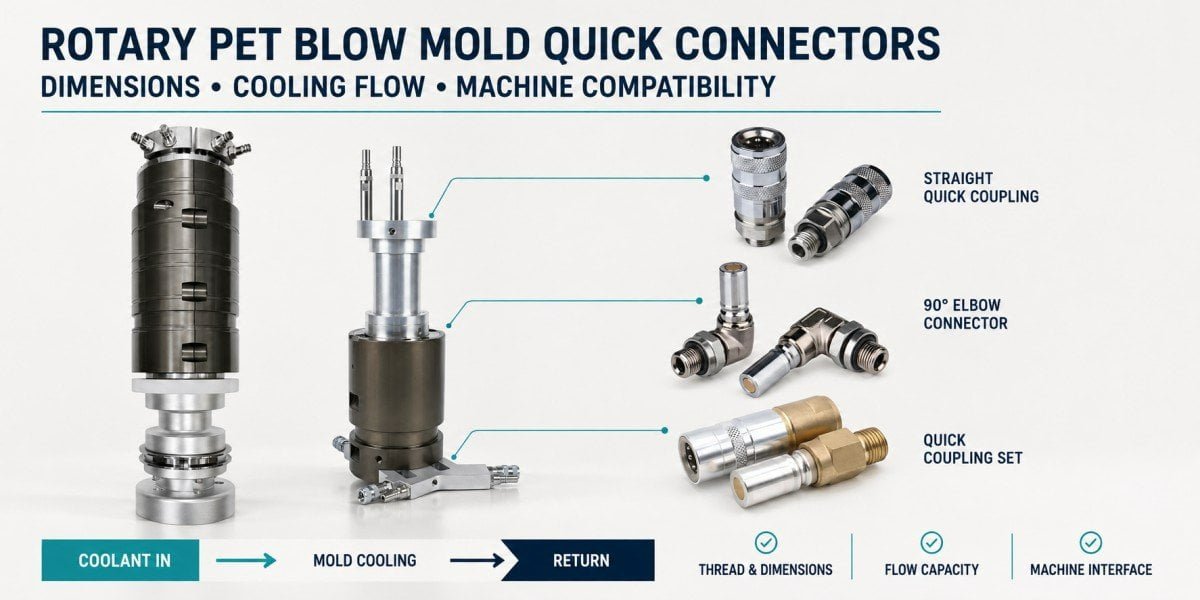
When buyers order a replacement rotary PET blow mold, most attention naturally goes to the bottle cavity, mold material, cooling channels, cavity pitch and mechanical interface.
The cooling quick connector is much smaller, so it is easy to treat it as a standard fitting that can be selected later.
From our blow mold manufacturing experience, that is not a good assumption.
A rotary PET blow mold quick connector is part of the mold-to-machine cooling interface. It must match the existing machine not only by thread, but also by mating profile, installation length, connector direction, available space, internal flow passage, sealing arrangement and cooling-circuit requirements.
A mold can be machined correctly and still create an installation problem if its cooling connectors do not match the machine.
For this reason, when we manufacture replacement rotary blow molds for existing equipment, we prefer to confirm the cooling interface before the mold design is frozen rather than selecting connectors after CNC machining has already been completed.
The engineering principle behind this article is simple:
A quick connector is not just a plumbing fitting attached to a blow mold. It is part of the replacement mold compatibility system.
Why Are Quick Connectors Critical on Rotary PET Blow Molds?
Rotary PET blow molds require reliable cooling while also supporting efficient mold changeovers. Quick connectors allow cooling circuits to be connected and disconnected without repeatedly dismantling conventional threaded pipework, but the connector must still preserve the required mechanical fit, sealing and hydraulic performance of the machine-mold interface.
Cooling is a functional part of PET stretch blow molding.
The heated preform expands against the mold cavity, and heat must be removed from the newly formed container before it leaves the blowing station. The importance of bottle-base cooling can be seen directly in Sidel’s StarLITE-R CSD technology, where Sidel describes an external mould base cooling circuit focused on warmer bottle-base zones, combined with internal base cooling through the stretch rod.
At the same time, a high-speed rotary blow molding machine is expected to change bottle formats efficiently.
Krones states that its MouldXpress automatic system can complete a blow-mold changeover in approximately 15 minutes under the specified conditions, while KHS describes its Speed-Loc system as allowing mold pairs and bases to be changed quickly on rotary InnoPET equipment.
This combination explains why the cooling connection matters.
The mold needs a water circuit during production, but that circuit must also be disconnected when the mold is removed.
If every format change required operators to rebuild several conventional threaded pipe joints around each cavity, changeover would become slower and more difficult to standardize.
A quick connector provides a much more practical interface.
But “quick” does not mean “universal.”
The connector still has to match the machine-side coupling and the physical space of the blow station. If the plug profile is wrong, it will not connect. If the installed length is wrong, the connector may sit at the wrong position. If its direction is unsuitable, the hose or machine structure may interfere.
That is why we treat the cooling connector in the same way we treat other replacement tooling interfaces.
It has to be designed for the machine that will actually use the mold.
This is consistent with the broader tooling principle discussed in our article High-Speed Rotary Blow Molds for Krones & Sidel: A Guide to Premium Compatible Tooling: rotary replacement molds should be matched to the actual equipment configuration rather than treated as generic cavities.
What Does the Supplied KⅡ Quick-Connector Catalog Tell Us?
The KⅡ catalog supplied for this article demonstrates why connector selection cannot be reduced to one thread specification. Within the same product family, connectors with a 6 mm nominal passage are offered with different threads, body diameters, installation lengths, straight or elbow layouts and pressure ratings.
The drawing you supplied is useful because it shows actual connector dimensions instead of only product photographs.
Several representative entries illustrate the engineering problem.
| Example from supplied KⅡ catalog | Thread / connection | Overall length L | Body diameter D | Rated pressure | Nominal bore |
|---|---|---|---|---|---|
| Coupler version | M16×1.5 | 60 mm | 23 mm | 50 bar | 6 mm |
| Coupler version | G1/4 | 60 mm | 23 mm | 50 bar | 6 mm |
| Plug version | G1/4 | 57 mm | 16.5 mm | 50 bar | 6 mm |
| Plug version | M16×1.5 | 57 mm | 16.5 mm | 50 bar | 6 mm |
| Compact plug version | M14×1.5 | 42 mm | 16.5 mm | 50 bar | 6 mm |
| Long G1/4 plug option | G1/4 | 76 / 92 / 110 / 122 mm | 16.5 mm | 50 bar | 6 mm |
The catalog also contains other configurations, including a 30-bar-rated entry and both straight and 90-degree connector arrangements.
The important point is not that one of these dimensions is universally correct for rotary PET molds.
It is the opposite.
One connector family itself already contains several geometrically different parts.
For example, a G1/4 connector can be short or extended. A plug with the same nominal 6 mm passage can have a different overall length from another version. A 90-degree body occupies a completely different space around the mold compared with a straight plug.
So when a customer sends us a photograph and says:
“Please use this type of connector.”
the photograph is useful, but it is not always enough.
We still want to know what is actually installed on the existing mold.
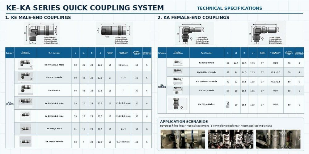
For the published article, I recommend using the catalog image here. It directly supports the discussion of thread size, L/L1 dimensions, body diameter, straight/elbow configuration, rated pressure and 6 mm nominal bore.
Which Connector Dimensions Must Match the Existing Blow Molding Machine?
Thread compatibility is only the first mechanical check. A replacement connector also has to place its mating end in the correct position inside the blow station, so overall length, installed length, body diameter, hex size and connector orientation can be just as important as the mounting thread.
Consider the KⅡ examples in the supplied drawing.
Several models use a 6 mm nominal bore and 50-bar rating, yet their total lengths are not the same.
One G1/4 plug is shown with an overall length of 57 mm. Another G1/4 straight version is approximately 54 mm. Extended G1/4 versions are shown in lengths of 76, 92, 110 and 122 mm.
Hydraulically, they may all belong to the same general flow-size family.
Mechanically, however, they are clearly not identical.
This distinction matters on a rotary blow molder because the connector has to meet the machine-side coupling at a specific physical location.
Suppose the mounting thread in the new blow mold is correct, but the selected plug protrudes 15 or 20 mm farther than the original part.
The question is no longer:
“Can it be screwed into the mold?”
The real questions become:
“Will it still align with the machine-side coupling?”
and:
“Is there still enough space around it during mold installation and machine operation?”
Similarly, if the connector body is larger than the original one, a nearby mold structure, cooling tube, clamp or machine component may become relevant.
This is why dimensional drawings are much more valuable than relying only on thread information.
Stäubli’s connector-selection guidance makes the same general distinction: connector size is defined by physical length and outside diameter, while passage diameter is a separate parameter affecting fluid-flow performance.
For replacement molds, we therefore treat the connector as a small three-dimensional machine interface.
Thread compatibility tells us whether it can be mounted. Dimensional compatibility tells us whether it can actually work in the available blow-station space.
This is the same reason we do not manufacture the rest of a rotary replacement mold from bottle CAD alone. Our article Custom Blow Molds: 4 Reasons Your New Mold Won’t Fit Your Blowing Machine explains why physical machine interfaces must be confirmed before tooling is finalized.
M16×1.5, G1/4 and M14×1.5: Why Thread Type Cannot Be Guessed
M16×1.5, M14×1.5 and G1/4 are not alternative names for the same connection. The M designations belong to the ISO metric-thread system, while G threads are parallel pipe threads. A replacement mold should therefore use the confirmed thread specification rather than selecting a connector from appearance alone.
The KⅡ catalog you supplied is a useful example because all three designations appear in one product series.
At first glance, the threaded ends are all relatively small metal fittings.
In a photograph, particularly when the connector is already installed in a mold, it can be difficult to judge thread form and pitch accurately.
But the standards behind the designations are different.
ISO 261 defines the general plan for ISO general-purpose metric screw threads designated with M, while ISO 228-1 covers parallel pipe threads used for mechanical assembly of fittings and related components.
That difference is important.
M16×1.5 tells us that the nominal metric diameter is 16 mm and the stated pitch is 1.5 mm.
M14×1.5 is a different metric diameter even though the pitch shown in the catalog is also 1.5 mm.
G1/4 belongs to a different thread family.
It should not be treated as a substitute for either metric connection.
There is another subtle point with G threads.
ISO 228-1 specifies parallel threads where the pressure-tight joint is not intended to be created by sealing on the thread itself. The standard explains that sealing, where required, is achieved at surfaces outside the threads with an appropriate seal.
This matters when reproducing an existing cooling interface.
It is not enough to confirm that the thread “turns into the hole.”
We also need to understand how the original connector is sealed against the mold.
A replacement fitting that has the correct nominal thread but the wrong sealing arrangement can still produce an unreliable connection.
For that reason, when the customer does not know the connector model, we prefer physical identification and measurement over guessing.
A clear photograph can start the discussion.
A thread gauge, dimensional measurement, existing part number or original mold drawing can finish it.
Why Can Two Quick Connectors With the Same G1/4 Thread Still Be Incompatible?
Because the mounting thread and the quick-coupling interface are two different things. Two fittings may both screw into a G1/4 mold port while using different plug profiles, coupling diameters, locking arrangements, exposed lengths or valve structures. Matching the mold thread does not prove that the connector will mate with the machine-side socket.
This is one of the most important distinctions in the article.
Buyers often think about the connector from the mold side:
“Both are G1/4, so both should fit.”
They may indeed both fit the threaded port in the mold.
But what happens at the other end?
The quick connector also has a male/female mating profile.
That profile determines whether the machine-side coupler and mold-side plug can connect and lock correctly.
Commercial quick-coupling manufacturers treat these as separate specifications. Parker, for example, lists interchange type, body size and thread connection as distinct product characteristics in its quick-coupling families.
That is a useful way to understand rotary blow-mold cooling connectors.
The mounting thread answers:
How does this component attach to the mold?
The quick-coupling profile answers:
What machine-side component can connect to it?
Those are not the same question.
This also means that changing connector brands needs care.
Even when two manufacturers offer G1/4 threaded plugs with a similar outside appearance, interchangeability should be confirmed from the specific coupling series or dimensional standard rather than assumed.
From our mold-manufacturing perspective, the safest reference for a replacement project is often the existing connector itself.
If the existing mold is running correctly, it gives us a physical benchmark for both sides of the problem: how the part attaches to the mold and how it connects to the machine.
Straight or 90-Degree Elbow: How Does Connector Direction Affect Mold Installation?
Straight and 90-degree quick connectors can serve the same cooling circuit but occupy different installation envelopes. The correct direction depends on the physical blow station, hose or coupling approach, mold installation movement and available clearance—not simply on which connector is easier to purchase.
Your supplied catalog shows this clearly.
There are straight connector versions as well as 90-degree elbow configurations.
Why would a rotary mold use one instead of the other?
Imagine a cooling port located on the side of a mold.
With a straight connector, the complete plug projects directly away from the port.
That may be ideal if the machine-side coupling approaches from the same direction and sufficient axial clearance is available.
But if another part of the blow station is close to the port, the same straight connector may protrude into an occupied area.
A 90-degree connector changes the direction of the connection and may allow the cooling line to remain closer to the mold.
However, the elbow itself occupies radial space in another direction.
So it is not correct to say that the elbow is always “more compact.”
It is compact in one direction and larger in another.
This is why connector direction has to be evaluated in the complete station assembly.
The issue becomes even more important when changing molds.
A rotary mold must be inserted, positioned and locked in the blowing station. A connector that does not interfere during normal production could still interfere with installation movement if its orientation is not considered.
The cooling line should also not be forced into an unreasonable bend simply because the new fitting exits in the wrong direction.
Mold designers already make similar decisions for cooling-system fittings in other tooling industries. HASCO, for example, offers both straight and 90-degree temperature-control fittings as separate geometric configurations, reinforcing the general principle that direction is a design variable rather than an interchangeable cosmetic feature.
For a rotary PET replacement mold, we therefore ask:
Where does the machine-side cooling connection actually approach the mold?
Once that is known, straight versus elbow becomes an engineering decision rather than a catalog preference.
Does the Connector Bore Size Affect Blow Mold Cooling Performance?
Yes, the connector passage contributes to the hydraulic resistance of the cooling circuit. However, a larger nominal bore does not automatically mean better mold cooling. The machine supply, hoses, couplings, internal valve geometry and mold cooling channels all operate as one hydraulic path and should be evaluated together.
Your KⅡ catalog lists a 6 mm nominal bore for many of the shown configurations.
That is useful information.
But it should not be interpreted as:
“6 mm is the standard bore for all rotary PET blow molds.”
The catalog proves only that these particular connector models use that nominal passage.
Different machine families, cooling circuits or connector systems can use other sizes.
The reason passage size matters is fluid resistance.
Cooling water has to pass through the connector before it reaches the mold circuit. If the connector creates a much smaller effective flow area than the surrounding system, it can contribute additional pressure loss.
Professional coupling manufacturers therefore publish flow-versus-pressure-drop information.
Parker’s thermal-management catalog, for example, separately gives nominal diameters of 3, 6, 9 and 12 mm for one coupling family and publishes water-flow pressure-drop curves for those sizes. The curves show a basic hydraulic principle: flow rate and pressure drop are linked, and the internal design and nominal diameter of the connector affect that relationship.
Stäubli similarly states that the passage diameter influences flow efficiency and should be matched to the system requirements to avoid excessive restriction.
However, this does not justify the opposite conclusion:
“Use the largest connector available and cooling will improve.”
Imagine that the mold contains small cooling passages downstream of the connector.
Increasing only the connector bore does not enlarge those mold channels.
Or imagine that the machine-side cooling circuit itself supplies a limited flow.
Again, installing an oversized connector does not create additional water by itself.
This is why we prefer to think of the cooling circuit as one path:
machine supply → machine-side coupling → mold-side quick connector → internal mold channels → return connection → machine return circuit
The narrowest or most restrictive areas anywhere in that path can influence the hydraulic result.
For PET blow molds, cooling performance should ultimately be judged at the circuit level rather than from one fitting diameter.
Sidel’s StarLITE-R example is useful here because its published engineering description does not treat the base connector as the cooling solution. It refers to a mould base cooling circuit targeted at the warmer base region. The circuit design is the functional system; the connector is one interface within it.
Can We Calculate Cooling Flow From a 6 mm Bore Alone?
No. Nominal bore does not provide enough information to calculate the actual cooling-water flow through a quick connector. Valve geometry, coupling profile, fluid properties, upstream pressure, downstream pressure and the rest of the circuit resistance are also required.
This is an important technical limit.
A low-quality connector article may see “6 mm bore” in a catalog and then publish a theoretical flow number.
We should not do that.
A quick coupling is not normally a simple 6 mm straight tube.
Many designs include valves, sealing surfaces, changes in internal cross-section and locking components.
Those details can substantially affect the effective flow resistance.
This can be seen directly in manufacturer data.
Parker does not define cooling performance from nominal diameter alone. It publishes measured or specified pressure-drop curves showing how flow changes with pressure loss for complete coupling designs.
Stäubli also separates nominal diameter, maximum allowable pressure and flow/pressure-drop performance in its coupling specifications.
Therefore, if we want to confirm whether a connector is hydraulically suitable for a specific rotary mold, the better data are a manufacturer flow curve or pressure-drop coefficient for the actual connected pair.
If that information is not available, it is safer to reproduce a known working connector specification from the existing machine than to invent a flow assumption.
This is exactly the type of situation where replacement mold manufacturing should be conservative.
If the original machine uses a proven connector family and the cooling circuit already performs correctly, changing to a different internal flow design should have a clear reason.
Does a 50-Bar Rated Connector Mean the Blow Mold Runs at 50 Bar?
No. A 50-bar connector rating describes a pressure capability assigned to the connector itself; it does not prove that the rotary blow mold cooling circuit actually operates at 50 bar. Actual cooling pressure and flow must be confirmed from the specific blow molding machine and cooling system.
This point is especially important because your supplied KⅡ catalog includes several models marked with 50 bar rated pressure, while another entry is marked 30 bar.
It would be technically incorrect to look at the table and write:
“Rotary PET blow mold cooling water operates at 50 bar.”
The catalog does not say that.
It tells us something about the connector.
Stäubli’s engineering guidance distinguishes nominal pressure from pressure drop and explains that nominal pressure refers to the pressure level associated with the connector’s design for operation, while pressure drop is the reduction that occurs through the connector as fluid flows.
Parker does the same thing in its cooling-coupling documentation: maximum working pressure is specified as one property, while flow-versus-pressure-drop charts are supplied separately. For one thermal-management family, Parker lists a maximum static working pressure of 20 bar while separately showing the hydraulic pressure loss at different water-flow rates.
This distinction is fundamental.
There are at least three different pressure concepts that should not be mixed:
the pressure capability of the connector, the actual supply pressure of the machine cooling circuit, and the pressure drop through the circuit while water is flowing.
They are related, but they are not interchangeable numbers.
For a replacement rotary blow mold, the correct approach is therefore not:
“The connector says 50 bar, so the mold cooling system is 50 bar.”
It is:
“The selected connector rating must safely suit the actual machine cooling conditions, which need to be confirmed separately.”
The same caution applies to temperature ratings, seal materials and coolant compatibility.
Those properties belong to the connector specification and should be compared with the real working fluid and machine conditions.
Why Are Sealing and Repeated Connection Important on High-Speed Rotary Blow Molds?
A rotary-mold cooling connector must seal reliably not only during its first installation but also through repeated production changeovers. The mating plug and coupler, valve structure, seals and connection condition should therefore be considered as a working pair rather than two isolated fittings.
Leakage around a mold cooling connector is more than a minor housekeeping issue.
Water is being introduced into an area containing precision tooling and moving machine components.
A leak can wet the mold area, complicate cleaning, affect maintenance work and make it more difficult to maintain a controlled production environment.
This is why cooling-coupling manufacturers invest considerable attention in connection sealing.
The KⅡ catalog supplied for this article describes a double-sealing design and a flat anti-spill interface as product features.
Those design ideas are also common in international cooling-coupling technology.
Parker’s thermal-management couplings use dry-break flat-face valve designs intended to minimize fluid loss during connection and disconnection, while Stäubli offers non-spill and flat-face coupling technologies for cooling applications.
For rotary PET molds, the repeated-changeover aspect is particularly relevant.
Krones and KHS both promote rapid mold-change technologies because beverage lines may need to switch between container formats efficiently.
Every time the mold is changed, the cooling connection may also be handled.
So a connector should not be evaluated only by asking:
“Does it seal when new?”
We also care about whether the mating surfaces are clean, whether the locking mechanism is in good condition, whether seals are worn, and whether the connector has been repeatedly connected in the intended alignment.
A connector that is difficult to insert can also indicate another compatibility problem.
Forcing the connection should not be treated as normal.
If the old and new molds place the connector in slightly different positions, the operator may still be able to push the connection together manually, but that does not prove the geometry is correct.
Repeated side loading or misalignment can accelerate wear at the interface.
The safest replacement design is one that reproduces the intended location naturally.
Why Should We Check Both the Male Plug and the Machine-Side Coupler?
A replacement mold supplier should not verify only the mold-side connector. Quick-connect compatibility exists between two mating components, so the machine-side socket, its location and its coupling profile are part of the same engineering check.
This sounds obvious, but it is an easy detail to miss.
A customer may remove an existing mold and photograph the small male plug installed in it.
We receive the photo and reproduce something that looks similar.
But the real functional interface is not the plug alone.
It is:
plug + coupler
The machine-side coupler determines what plug profile is accepted, how deeply it inserts, where the locking surfaces engage and where the seals operate.
The supplied KⅡ catalog itself separates male and female connector categories, which is a useful reminder that the complete system consists of two halves.
Professional quick-coupling catalogs follow the same structure.
Parker distinguishes couplers and nipples/plugs within defined interchange families rather than treating every fitting with the same thread as automatically compatible.
For this reason, if we are not certain of the existing connection series, we may ask the customer for photographs of both sides.
Where possible, the existing connector part number is even better.
For an older production line, this matters because the machine may no longer be in its exact original configuration.
Previous owners or maintenance teams may already have replaced some cooling components.
So machine model alone does not always tell us which quick connector is physically installed today.
For replacement tooling, actual equipment should remain the final reference.
How Do Quick Connectors Affect Mold Cooling Maintenance?
Quick connectors make cooling circuits easier to disconnect during mold change and service, but they also introduce components that should be inspected for seal condition, contamination, wear and flow restriction. Cooling maintenance therefore includes both the internal mold circuit and its external connection points.
A cooling channel can be machined correctly and still perform poorly if the external connection is restricted.
Likewise, a good connector cannot compensate for blocked or scaled internal channels.
This is why mold maintenance should treat the water circuit as one system.
During long-term production, cooling circuits can accumulate deposits depending on water quality and operating conditions. Seals in connection components also experience mechanical use during repeated connection cycles.
If a connector starts leaking, simply tightening or forcing it repeatedly is not always the correct solution.
The condition of the sealing surface and mating part should be checked.
If the cooling flow appears reduced, the connector is one possible restriction point, but the internal circuit should also be inspected before assigning the problem to one component.
Our PET Blow Mold Preventive Maintenance: A Complete Guide for Aluminum and Stainless Steel Tooling discusses the broader maintenance logic for production molds.
For quick connectors, the most useful maintenance mindset is:
Do not inspect only for leakage. Inspect whether the connector still performs its mechanical and hydraulic function.
Do Krones, Sidel and KHS Rotary Blow Molds Use One Universal Cooling Connector?
No universal connector should be assumed across Krones, Sidel, KHS or even across different machines from the same brand. Rotary mold tooling and changeover systems are machine-specific, so the existing machine configuration and installed cooling interface should be used as the project reference.
The temptation to generalize is understandable.
A buyer may ask:
“Which connector is used on Krones molds?”
as if there were one part number covering every Contiform generation.
Or:
“Which connector should I use for a Sidel rotary mold?”
The equipment families are too broad for that approach.
Krones has developed multiple generations of Contiform equipment and different changeover configurations. KHS similarly uses different generations of InnoPET Blomax and Speed-Loc-based tooling concepts. Sidel offers a wide range of EvoBLOW configurations and mold-change systems.
Even within official Krones listings, equipment configuration is specific enough that individual machines are described with options such as base quick-change or quick-change units for the bottom mold.
That does not tell us which KⅡ, Stäubli, Parker or other connector a particular customer currently uses.
It tells us something more important:
the real machine configuration matters.
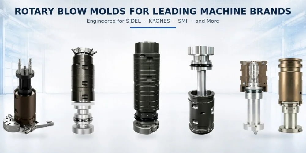
When we manufacture a rotary replacement mold, we therefore prefer to work from the customer’s actual mold and machine information.
Our Semi-Auto vs. Fully Auto PET Blow Molds and Mechanical Compatibility article explains the broader reason: PET blow molds are not mechanically universal across machine platforms.
The cooling connector is one more interface where that principle applies.
What Should Be Confirmed Before Selecting Quick Connectors for a Replacement Rotary Blow Mold?
Before choosing the cooling connector, first identify the actual machine and existing mold interface. Then confirm the connector series, mating profile, mounting thread, installation geometry and cooling-path requirements. The selection should be frozen together with the mold interface—not treated as a hardware purchase after CNC machining.
When we receive an inquiry for a replacement Krones, Sidel, KHS or another rotary blow mold, we prefer to begin with the mold already running in the machine.
The existing tooling tells us a great deal.
We can see where the cooling connectors are located and how they approach the machine-side couplings.
If the existing mold is available for measurement, we can check the mounting thread, connector body, exposed length and orientation.
If it is not possible to send the mold, clear dimensional photographs and the connector part number are useful alternatives.
Then we look at the machine side.
This is where we confirm whether the connector is a standard mating series or a machine-specific configuration and whether the socket position imposes any dimensional restriction.
Only after that should the cooling-channel design and connector location be finalized in the new mold CAD.
From our manufacturing perspective, this sequence is safer than finishing the mold first and trying to find a connector afterward.
The difference may appear small on a single cavity.
On a high-cavity rotary system, however, repeating the wrong interface across every station creates a much larger correction project.
Imagine a 20-cavity mold set where every male cooling plug has been positioned several millimetres away from the machine-side coupling center.
The connectors themselves may not be expensive components.
Correcting twenty finished mold assemblies is a different matter.
This is why we treat connector confirmation as part of the design-release process.
For a replacement project, the best rule is:
Confirm the machine-side mating connector first. Confirm the mold-side thread and installation geometry second. Confirm the cooling-path requirement third. Then freeze the mold interface.
That order is far more reliable than selecting a connector from appearance after machining.
What We Check From a Customer’s Existing Connector
When the original machine documentation is incomplete, the existing working connector can provide the best reference. We use it to establish both the mold-side mounting geometry and the machine-side mating requirements before deciding whether the same part or a compatible alternative should be used.
This is a common situation with older rotary equipment.
The customer may have the machine but not the original complete tooling drawings.
Or the mold may have been manufactured by another supplier many years ago.
In that situation, we do not need to guess immediately.
The current connector itself contains useful engineering information.
The threaded end tells us how it mounts into the mold.
The body geometry shows how much space it occupies.
The exposed plug length shows where the machine-side coupler expects to meet it.
The connector direction shows how the existing machine approaches the cooling circuit.
The mating profile tells us which socket family must be retained.
And if a part number or manufacturer mark is visible, it can allow the specification to be confirmed against the correct catalog.
This is one reason photographs are helpful, but we normally prefer a photograph taken together with measurement references rather than a distant picture of the complete mold.
A ruler or caliper reading next to the part can answer questions that visual appearance cannot.
If the thread is uncertain, physical thread measurement is still better than guessing from connector diameter.
This is particularly important for the combinations shown in your supplied catalog.
M16×1.5, M14×1.5 and G1/4 can all appear in relatively compact connectors, but they represent different interfaces.
FAQ
Are PET blow mold quick connectors universal between different blow molding machines?
No. They should not be assumed to be universal. Different machines and mold configurations can use different mating profiles, mounting threads, installed lengths, connector directions and available spaces. Even when two connectors look similar, replacement tooling should be checked against the actual machine-side coupling before compatibility is confirmed.
Can two quick connectors with the same thread size be interchangeable?
Not necessarily. The same G1/4 or M16×1.5 mounting thread only tells us that the connector may fit the same threaded port. The quick-coupling plug profile, body size, exposed length, valve design, nominal bore and straight/elbow geometry can still differ. The mating series must also match the machine-side coupler.
Does a larger quick-connector bore always improve mold cooling?
No. The connector is only one part of the cooling circuit. A larger passage may reduce one source of restriction, but actual mold cooling also depends on the machine supply, hoses, mating coupling, internal mold channels, coolant properties and total pressure drop. Professional coupling manufacturers therefore evaluate flow together with pressure loss rather than judging performance by bore alone.
Does a 50-bar connector rating mean the PET blow mold cooling pressure is 50 bar?
No. The 50-bar value shown in the supplied KⅡ catalog is a connector rating, not evidence that the blow molding machine cooling circuit operates at 50 bar. Connector pressure capability, actual system pressure and hydraulic pressure drop are different parameters and should be confirmed separately.
What information is needed to match quick connectors for a replacement rotary blow mold?
The most useful information is the exact blowing-machine model and actual configuration together with photographs or part numbers of the existing mold-side and machine-side connectors. Existing mold drawings are particularly valuable. If drawings are unavailable, the connector thread, body dimensions, installed length, orientation, mating profile and nominal passage should be measured before the new mold interface is frozen.
Conclusion
The quick connector may be one of the smallest components on a rotary PET blow mold, but it sits at a very important boundary.
On one side is the blow mold and its cooling circuit.
On the other side is the existing blow molding machine.
That is why we do not treat it as a fitting that can always be purchased at the end of the mold project.
Your KⅡ connector catalog illustrates this clearly.
Within one series we can already see M16×1.5, M14×1.5 and G1/4 connections. We can see straight and 90-degree versions. We can see different overall lengths and installation dimensions. Many versions use a 6 mm nominal bore and are rated at 50 bar, while another catalog entry has a different pressure rating.
Those numbers do not tell us that one connector is universally suitable for a Krones, Sidel or KHS mold.
They tell us exactly why the actual interface needs to be checked.
The thread must fit the mold.
The quick-coupling profile must fit the machine-side socket.
The overall geometry must fit the available blow-station space.
The connector direction must suit the physical installation.
The internal passage must be appropriate for the complete cooling circuit.
The sealing system must remain reliable during repeated mold changeovers.
And the connector’s pressure rating must be suitable for the actual system conditions without being confused with the machine’s real cooling operating pressure.
From our manufacturing experience, this is especially important on replacement rotary PET blow molds.
When a new mold is being designed for an existing machine, we already have a proven reference sitting in the customer’s factory: the mold that is currently running.
We prefer to copy and verify that working interface before making changes.
If the customer wants to use another quick-connector model, we then compare the new connector against the original mechanically and hydraulically rather than assuming that one matching thread is sufficient.
For customers planning replacement tooling for an existing Krones, Sidel, KHS or other rotary PET blower, you can send PETMOLDER the machine model and nameplate, existing mold drawings or photographs, connector photographs and part numbers, cooling-port dimensions, cavity number, cavity pitch and any available machine-side connector information.
We can verify the cooling interface together with the rest of the tooling before manufacturing begins.
When manufacturing a replacement rotary blow mold, cooling connector compatibility should be confirmed before the mold interface design is frozen—not after CNC machining is completed.
Related PETMOLDER Articles
- High-Speed Rotary Blow Molds for Krones & Sidel: A Guide to Premium Compatible Tooling
- Custom Blow Molds: 4 Reasons Your New Mold Won’t Fit Your Blowing Machine
- Semi-Auto vs. Fully Auto PET Blow Molds and Mechanical Compatibility
- PET Blow Mold Preventive Maintenance: A Complete Guide for Aluminum and Stainless Steel Tooling
- Why Are Most PET Blow Molds Made of Aluminum? 4 Engineering Reasons Explained