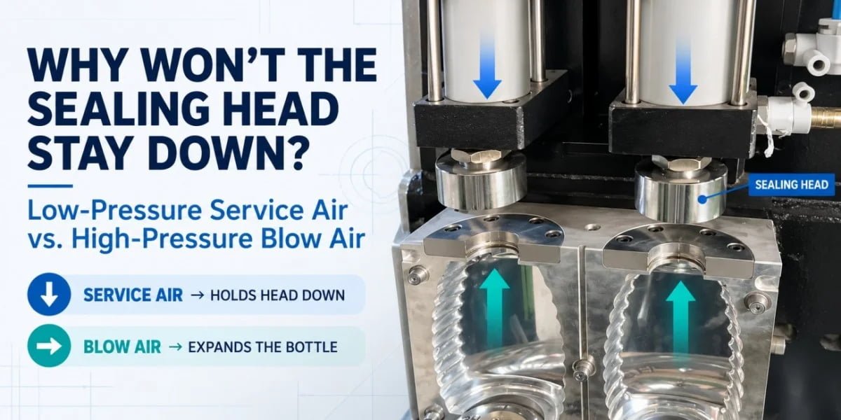
When the sealing head of a semi-automatic PET blow molding machine lifts or loses contact with the preform as blowing begins, increasing air pressure is usually not the right response. The PET blow molding sealing head must receive the pressure and pneumatic control intended for the machine-action circuit, while high-pressure blow air should remain dedicated to bottle formation. Mixing these two functions can destabilize the entire blowing sequence.
This type of problem is particularly common during the commissioning of small semi-automatic PET bottle lines. A new operator may understand that PET bottles require high-pressure compressed air, but it is easy to overlook the fact that the same machine may also require a much lower and independently controlled pressure for pneumatic actions.
From our manufacturing and commissioning experience, this distinction should be understood before bottle temperature, mold design, or blowing parameters are adjusted.
If the machine cannot first hold the blow nozzle or sealing head correctly against the preform neck, the PET bottle does not yet have a stable condition for blowing.
The problem is therefore not simply:
“Do we have enough compressed air?”
The more important question is:
Is the correct air pressure being supplied to the correct machine circuit?
Tanzania Case: Why the Sealing Heads Lifted When Blowing Started
A two-cavity semi-automatic PET blower supplied to a customer in Tanzania showed a clear commissioning problem: the sealing heads could move downward toward the preforms, but when blowing started, they could not remain in a stable sealing position. The root cause was on the pneumatic side rather than in the blow mold.
The customer had received the machine and was beginning the initial production setup.
High-pressure compressed air was available because the customer understood that PET stretch blow molding requires substantial pressure to form the bottle. However, the machine’s low-pressure pneumatic functions had not been supplied through a correctly controlled service-air condition.
During testing, both sealing heads could descend toward the preform necks. At first glance, the machine appeared ready to blow.
The problem became obvious as soon as the blowing cycle started.
The sealing heads reacted abnormally and moved upward instead of maintaining their intended sealing positions. High-pressure air then escaped around the neck and nozzle area rather than entering the preform under a stable sealed condition.
At that point, continuing to adjust preform heating would not have solved the problem.
Changing the blow mold would not have solved it either.
Increasing the high-pressure blowing time would only have supplied more air to a system that had not yet established the required seal.
The first useful clue was that the same type of abnormal reaction occurred on the two-cavity machine rather than appearing as an isolated bottle defect in only one mold cavity.
That made the common pneumatic system much more important in the diagnosis.
After reviewing the air arrangement, the key issue became clear: high-pressure air was available, but the machine did not have the correct reduced-pressure condition for the pneumatic service functions involved in sealing and related machine actions.
The corrective direction was therefore to separate the pressure requirements.
High-pressure air remained available for bottle blowing, while the relevant service-air branch was supplied through suitable pressure reduction and air treatment according to the machine requirements.
For this particular Tanzania troubleshooting case, the reduced-pressure branch was adjusted to approximately 8–10 bar.
This number should not be copied as a universal setting for every semi-automatic PET blower. Different machines use different cylinder sizes, valves, pneumatic arrangements, and operating specifications. The correct service-air pressure must follow the actual pneumatic diagram and machine manufacturer’s requirements.
Once the machine actions were supplied under the appropriate pressure condition, the sealing heads could establish a much more stable operating position and the blowing sequence could proceed normally.
The problem was not insufficient air pressure. The problem was using the wrong pressure for the wrong function.
What Is the Difference Between Service Air and High-Pressure Blow Air?
Service air operates pneumatic machine actions, while high-pressure blow air performs the actual bottle-forming work inside the heated preform. They may originate from the same compressed-air system on some machines, but they should not be treated as the same pressure circuit.
A PET blow molding machine may use compressed air for several different purposes during one production cycle.
The fact that all of these functions use air does not mean they should all receive the same pressure.
| Air Function | Main Purpose | Typical Role in the Machine |
|---|---|---|
| Service / action air | Controls pneumatic movement | Sealing cylinders, pneumatic actuators and other machine actions according to the specific design |
| Pre-blow air | Starts controlled preform expansion | Begins radial expansion while stretching is developing |
| High-pressure blow air | Completes bottle formation | Forces the PET against the blow mold cavity |
| Exhaust circuit | Releases bottle pressure | Safely discharges air after the forming stage |
On some semi-automatic machines, the mold movement, sealing mechanism, stretching system, or other actuators are pneumatically controlled. Other machines may use different mechanical arrangements.
For this reason, there is no reliable rule that says every sealing cylinder or stretch mechanism should operate at one universal pressure.
What matters is the machine design.
The pneumatic diagram should show which branch supplies the blowing circuit and which branch supplies the machine-action circuit.
This is where first-time users sometimes make a wrong assumption.
They know that a PET bottle may require high-pressure air during final blowing, so they assume that supplying the same pressure to a pneumatic cylinder will simply make the machine action stronger.
Pneumatic machines do not work that way.
A cylinder, valve, hose, regulator, sealing assembly, and mechanical stop are designed to operate within a defined pressure range. Supplying substantially more pressure changes the forces acting on the mechanism and may cause the system to react differently from its intended design.
High pressure forms the bottle. Service air controls the machine that forms the bottle.
Why Can the PET Blow Molding Sealing Head Lift During Blowing?
The sealing head must reach its designed position and remain stable while the blowing circuit is pressurized. If the sealing mechanism is exposed to an incorrect pneumatic condition, the balance of forces around the cylinder and nozzle assembly can change, causing abnormal movement or loss of sealing.
A blow nozzle does more than direct air toward the bottle.
Before the high-pressure forming stage can work correctly, the nozzle and preform neck must form a sufficiently stable air path.
The air should enter the preform and perform useful work expanding the PET.
If the sealing head moves away from the neck as the pressure rises, a significant amount of air can escape around the sealing interface instead.
This changes the entire process.
The pressure inside the preform no longer follows the intended blowing curve, and the bottle may fail to form correctly even when the compressor itself is capable of supplying sufficient high pressure.
In the Tanzania case, the abnormal movement was closely associated with the start of blowing.
This timing mattered.
Before high-pressure blowing started, the heads could move down. When the blowing stage began, the sealing condition became unstable.
That observation made it necessary to investigate how the service-air circuit and blow-air circuit interacted rather than immediately blaming the mold.
Pneumatic cylinder force is related to air pressure acting over the effective piston area. If the pressure supplied to the cylinder is changed substantially, the force generated by the actuator changes as well.
When a service circuit operates far outside the pressure condition for which it was designed, the cylinder may move abnormally or fail to hold the mechanism in its intended position. The excessive force can also increase the load on seals, guides, valves, and mechanical components. In addition, an unstable pneumatic condition can disturb the intended sequence between sealing, stretching, pre-blowing, and final blowing.
This does not mean that high pressure will make every sealing head move upward.
Machine designs differ. Cylinder orientation, valve logic, piston areas, mechanical stops, and sealing-head structures are not identical.
The correct conclusion is more specific:
If the sealing circuit operates outside its intended pressure range, the sealing mechanism may no longer move or hold in the way the machine designer intended.
What Should Happen Before High-Pressure Blow Air Enters the Preform?
High-pressure blow air should enter only after the machine has established the required mechanical position, neck sealing, stretching condition, and process sequence. A high-pressure supply cannot compensate for a sealing head that has not established a stable connection with the preform.
In a typical two-stage PET stretch blow molding process, the preform is first reheated to the required forming condition. It is then transferred to the blow mold, where several coordinated actions occur within a short cycle.
The mold closes around the heated preform.
The blowing nozzle or sealing head reaches its required position and establishes the air path through the neck area.
Stretching then controls the axial development of the preform. Pre-blow begins the early radial expansion under controlled conditions, and the final high-pressure blow completes the bottle against the mold cavity.
After sufficient forming and cooling, the air is exhausted and the mold opens.
These actions are connected. They should not be viewed as isolated machine movements.
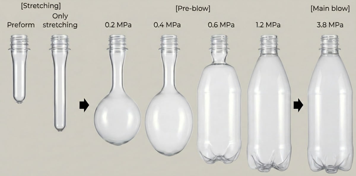
Readers who need a broader explanation of this sequence can refer to our guide to PET two-stage molding and the complete preform-to-bottle process.
If the sealing head is already unstable before the correct pre-blow and high-pressure stages have developed, troubleshooting the finished bottle is premature.
The first task is to establish a repeatable machine sequence.
Only after the nozzle seal is stable does it make sense to analyze bottle defects related to heating, stretching, pre-blow, wall distribution, or blow pressure.
Can One High-Pressure Compressor Supply Both Blow Air and Service Air?
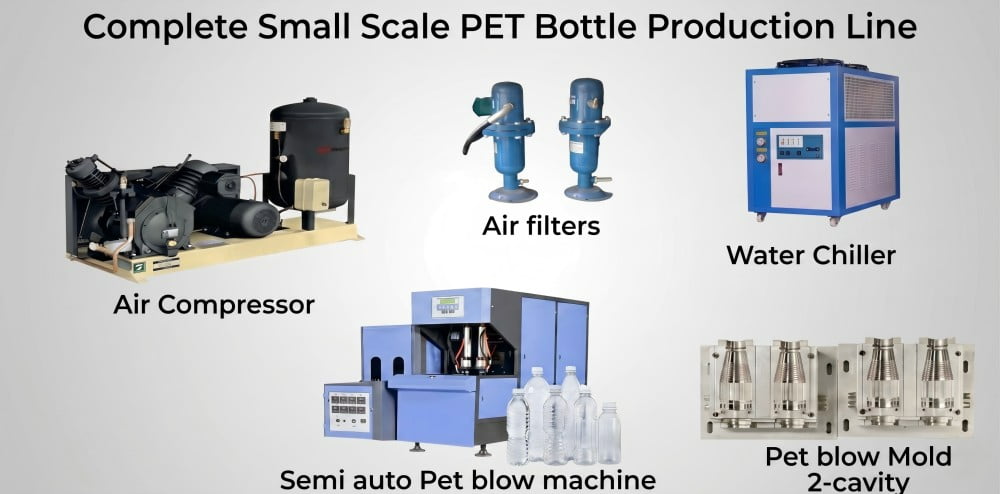
Some semi-automatic PET blow molding machines can use one suitable high-pressure air source to support more than one pressure level, provided the pneumatic system is intentionally divided and the service-air branch is reduced, treated, and controlled correctly.
This question matters for small PET bottle plants because purchasing two separate compressors is not always necessary for every machine configuration.
However, the answer depends on the actual equipment.
A simplified arrangement can use a high-pressure source feeding separate branches. One branch remains at the pressure required for PET bottle blowing. Another branch passes through pressure-reduction and air-treatment components before supplying pneumatic machine actions.
The two pressure requirements remain different even though the original compressed-air source may be shared.
This distinction is important.
Reducing the pressure of the entire line would not be a solution because the machine would then lose the high-pressure supply required for final bottle formation.
The objective is to create a controlled low-pressure branch while preserving the required high-pressure branch.
The arrangement must also provide sufficient air flow.
Pressure alone does not determine whether a pneumatic system will operate correctly.
A regulator can display the correct outlet pressure when the machine is idle and still fail to deliver enough flow when several actuators operate during the cycle. Undersized piping, filters, valves, regulators, or receiver capacity can all contribute to pressure drop during real operation.
Therefore, the air system should be evaluated in terms of both:
required pressure and required flow.
This is also why the compressor should not be selected only by looking at its maximum pressure rating.
A practical compressed-air system for a PET bottle line needs to consider compressor capacity, storage, air treatment, pressure stability, pipe sizing, and the actual consumption profile of the blow molding machine.
For factories planning the entire utility and equipment arrangement, our small-scale PET bottle production line guide explains how the blower fits together with compressors, auxiliary equipment, filling, and other production-line components.
Why Can’t You Install Any Low-Pressure Regulator on the High-Pressure Line?
A pressure regulator must be selected for the actual upstream pressure, required downstream pressure, and required air flow. The desired outlet setting alone is not enough to determine whether a regulator is suitable or safe.
This is an important point when a factory wants to derive service air from a high-pressure source.
An operator may see that the machine needs a lower service-air pressure and assume that a standard workshop regulator can simply be installed on the high-pressure line.
That should not be assumed.
The regulator is exposed to the inlet pressure before it reduces the air to the required outlet condition.
Therefore, its maximum inlet-pressure rating must be appropriate for the high-pressure side.
The same principle applies to every component connected to that part of the circuit. Filters, valves, fittings, hoses, gauges, manifolds, and piping must be rated for the pressures they can actually experience.
Flow capacity also matters.
A regulator that is pressure-rated but significantly undersized may create a large pressure drop every time the sealing cylinders or other actuators demand air.
That can produce a different type of instability even when the static pressure setting looks correct.
The correct approach is to begin with the machine’s pneumatic diagram and air-inlet specification.
The installer should confirm whether the machine has one air inlet or separate high- and low-pressure inlets, whether pressure reduction is already built into the machine, and what flow and pressure the service circuit requires.
Any modification to a high-pressure pneumatic system should use appropriately rated components and be carried out according to the machine manufacturer’s requirements by qualified personnel.
Why Does Air Quality Matter to the Sealing System?
Stable service-air pressure can still produce unreliable machine actions if the compressed air contains excessive moisture, contamination, or causes significant pressure loss through the treatment system.
Compressed air is not only an energy source. It is also the operating medium inside pneumatic valves and cylinders.
If water accumulates in the air system, corrosion and unstable pneumatic behavior can develop over time.
Particles can interfere with regulator and valve operation.
Poorly selected filters can create an excessive pressure drop when air demand rises.
Leaking fittings or damaged cylinder seals can consume air continuously, making the pressure at the actuator very different from the pressure indicated closer to the compressor.
For a sealing head, these problems may appear as inconsistent movement rather than a complete machine failure.
One cycle may look normal while the next behaves differently.
The sealing head may descend at different speeds, or it may reach the correct mechanical position but fail to maintain the same force during repeated production.
That is why a commissioning check should evaluate repeated cycles rather than judging the machine from one successful movement.
How Can You Tell Whether the Problem Is in the Common Air Supply or One Sealing Head?
The number of affected stations is one of the most useful clues. If both sealing heads on a two-cavity machine show the same abnormal reaction at the same stage of the cycle, common air supply and control conditions deserve priority. If only one head is affected, the local cylinder, valve, seal, or mechanical guide becomes more important.
| Observation | More Useful First Check |
|---|---|
| Both sealing heads lift when blowing begins | Common service-air pressure, regulator, valve logic, or shared machine sequence |
| Both heads move slowly | Common flow restriction, insufficient service-air supply, or pressure drop |
| Only one head lifts | Local cylinder, valve, hose, guide, or mechanical problem |
| Head reaches position but air still leaks | Nozzle seal, neck interface, sealing surface, or alignment |
| Head does not descend fully | Cylinder stroke, air supply, valve operation, or mechanical interference |
| Machine works for one cycle but becomes unstable during repeated cycles | Air recovery, receiver capacity, leakage, regulator response, or flow limitation |
This diagnostic logic was important in the Tanzania case.
When the same machine function behaves abnormally at both stations, it is less reasonable to immediately assume that two blow molds were manufactured incorrectly in exactly the same way.
The shared system should be investigated first.
The same reasoning can be useful in other multi-cavity PET blow molding problems.
A defect that repeatedly appears in only one cavity can point toward a local mold, stretch-rod, heating, alignment, or mechanical issue.
A defect that appears across all cavities at the same process stage often justifies checking a common machine or process variable first.
If both cavities fail during the same machine action, inspect the common machine system before blaming two molds at once.
What If the Sealing Head Stays Down but Air Still Leaks?
A sealing head that physically moves out of position and a sealing head that reaches the correct position but still leaks are different faults. Correct air pressure will not repair a damaged sealing surface or an incompatible preform neck.
This distinction is important because not every leak is caused by the service-air circuit.
If the head clearly remains in its designed position while high-pressure air escapes around the neck, the actual sealing interface needs closer inspection.
The nozzle seal may be worn or damaged.
The sealing head may be mechanically misaligned with the preform.
The preform neck may be deformed.
The neck finish may not correspond to the machine tooling.
The preform may also be sitting incorrectly in the mold or transfer position.
These conditions can create leakage even when the sealing cylinder itself is working correctly.
The neck area deserves particular attention because it is already injection-molded before the stretch blow molding process. It should not be distorted by the normal bottle-body stretching operation.
If neck geometry has changed before or during blowing, sealing reliability can be affected.
Our article on PET bottle neck deformation and ovality discusses neck deformation from the finished-package perspective. Although the failure mechanism is different, the same principle applies: the neck area must remain dimensionally controlled for downstream interfaces to work properly.
What Should Be Checked After the Service-Air Pressure Is Corrected?
The machine should not be considered repaired simply because the sealing head stops lifting. The entire blow cycle should be checked again to confirm that sealing, stretching, pre-blow, high-pressure blowing, and exhaust now occur consistently in the intended sequence.
After correcting the service-air condition on the Tanzania machine, the most important change was that the sealing heads could establish and maintain their operating position more reliably.
That allowed the remaining blow molding sequence to be evaluated under a stable condition.
The stretch mechanism should move through the intended stroke without abnormal acceleration or hesitation.
The sealing head should reach the correct position repeatedly, not only once.
Pre-blow should begin only under the intended process condition.
The high-pressure blow should enter after the required sealing and stretching conditions have been established.
Finally, the exhaust should release the internal bottle pressure correctly before the mold opens.
Both cavities should be observed through repeated cycles to confirm that they respond consistently.
This is particularly important when one compressed-air system supplies several machine functions. A static pressure gauge may look normal while the machine is stopped, but pressure can fall during a real cycle if the air supply or regulator cannot maintain the required flow.
Therefore:
Correct pressure is only useful when it reaches the correct actuator at the correct time.
How Is This Different From a Pre-Blow Pressure Problem?
A sealing-head problem occurs before or while the machine is trying to establish the air seal. A pre-blow problem occurs after a usable seal already exists and concerns how the heated preform begins to expand. Both involve compressed air, but they belong to different stages of troubleshooting.
| Condition | Sealing-Head / Service-Air Problem | Pre-Blow Process Problem |
|---|---|---|
| Main question | Can the machine establish and maintain the blow seal? | Is the preform beginning to expand correctly? |
| Main system | Service-air circuit and sealing mechanism | Pre-blow pressure, timing and stretch interaction |
| Typical symptom | Head lifts, cannot hold position, or air leaks before stable blowing | Bottle begins forming but material distribution becomes abnormal |
| Primary checks | Regulator, cylinder, valve, nozzle position, common air circuit | Pre-blow pressure, timing, stretch rod, heating and preform behavior |
| Possible result | Blow cycle cannot develop correctly | Gate shift, uneven wall distribution, incomplete forming or other bottle defects |
This distinction matters because both problems can occur on the same poorly commissioned machine.
The first problem is:
Can the machine hold the nozzle correctly?
Only after that condition is stable should the operator ask:
Is the preform expanding correctly?
For example, a preform gate that moves from the bottle base toward the heel or lower sidewall is a different defect. In that case, the machine may already be sealing successfully, but the interaction between stretching and early expansion can be incorrect.
The troubleshooting sequence should therefore remain:
Establish the seal first. Diagnose preform stretching and blowing second.
Why Can Incorrect Service-Air Pressure Affect More Than the Sealing Head?
If several pneumatic functions share the same service-air circuit, incorrect pressure can affect more than one machine movement. The exact symptoms depend on the individual machine design, but the sealing head may be only the most visible problem.
Some semi-automatic machines use pneumatic actuation for the stretch mechanism. Others may use pneumatic mold actions or additional cylinders and valves.
If all of these components receive pressure from the same service-air branch, an incorrect pressure condition can alter several movements at once.
A stretch cylinder may move faster or differently from the intended condition.
A pneumatic mold action may experience abnormal force.
Control valves can be exposed to pressure outside their intended operating condition.
Cylinder and valve seals may experience increased loading.
Most importantly, the timing relationship between several actions can change.
PET stretch blow molding depends on sequence as much as on pressure.
A cylinder that reaches its position too early or too late can affect what happens when the next valve opens.
This is why a good commissioning process does not treat each actuator as an independent component.
The pneumatic system should be evaluated as part of the entire machine cycle.
Why Should Buyers Request the Pneumatic Diagram Before Commissioning?
The pneumatic diagram tells the installer how the machine separates pressure functions, where pressure reduction occurs, which actuators share a circuit, and what must be connected externally. Without it, a factory can have a suitable compressor and still connect the machine incorrectly.
This is particularly important for buyers purchasing their first semi-automatic PET blower.
A supplier may tell the buyer that high-pressure compressed air is required.
That information alone is not enough to install the machine correctly.
The buyer should understand whether the machine has separate high-pressure and service-air inlets, whether pressure reduction is already built into the machine, and which air-treatment components are included.
The required flow should also be confirmed.
Compressor pressure without compressor capacity is only half of the specification.
The receiver tanks, dryers, filters, piping, and valves should be sized so that the required pressure remains stable during the actual production cycle.
This issue is one reason we recommend paying close attention to the first machine-and-mold commissioning stage. In our article on why the first PET blow mold should be carefully coordinated with the blow molding machine supplier, we explain why many apparent mold problems are actually revealed only when tooling, machine interfaces, and process conditions meet for the first time.
Pneumatic installation deserves the same attention.
A machine should not arrive at the factory as a collection of individual components that the operator must reverse-engineer during production trials.
The air requirements should be clear before commissioning begins.
What Should Buyers Confirm Before Ordering a Semi-Automatic PET Blower?
A buyer should ask for the complete compressed-air requirement rather than only the maximum blowing pressure. This should include every pressure level, the required flow, the number of air inlets, and whether pressure reduction and treatment are built into the machine.
| Information to Confirm | Why It Matters |
|---|---|
| High-pressure blow-air requirement | Determines the pressure needed for final bottle formation |
| Service-air requirement | Defines the operating condition for pneumatic machine actions |
| Pre-blow arrangement | Shows how early bottle expansion is controlled |
| Number of machine air inlets | Prevents incorrect installation |
| Required air flow | Helps size the compressor and piping correctly |
| Receiver requirement | Supports stable pressure during cyclic demand |
| Pressure-reduction arrangement | Clarifies whether it is internal or must be supplied externally |
| Filtration and drying requirement | Protects pneumatic and blowing components |
| Pneumatic diagram | Shows how the complete air system should be connected |
Buyers should also confirm which auxiliary components are included with the machine.
A quotation for a blow molding machine does not always mean that compressors, air tanks, high-pressure filters, dryers, chillers, or connecting piping are included.
This becomes especially important on small production projects where the customer may be purchasing the complete bottle-making system for the first time.
The blow mold itself should also be checked for mechanical compatibility with the machine. Our comparison of semi-automatic and fully automatic PET blow mold compatibility explains why tooling designed for one machine platform cannot automatically be assumed to fit another.
How We Resolved the Tanzania Sealing-Head Problem
The Tanzania machine did not require a blow-mold modification to correct the sealing-head behavior. The effective troubleshooting direction was to restore the correct relationship between high-pressure blowing air and the lower-pressure pneumatic service circuit.
The customer initially had the most important utility for PET blowing: high-pressure compressed air.
What was missing was the correct way to use that air for different machine functions.
Instead of treating high-pressure air as the direct supply condition for every pneumatic action, the air system was separated according to function.
The blow circuit retained the pressure required for forming the bottle.
The relevant service circuit received controlled reduced pressure through appropriately selected pneumatic components.
In this particular project, the service-air troubleshooting setting was approximately 8–10 bar.
Once that pneumatic condition was corrected, the sealing heads could maintain their operating position more reliably, allowing the blow cycle to proceed under a stable seal.
The key lesson was not the exact pressure number.
The key lesson was the system architecture.
High-pressure air remained high pressure where bottle formation required it. Lower-pressure service air was provided where the machine actions required it.
That is a much more important principle than copying one pressure setting from another machine.
A different semi-automatic blower may use a different service pressure, different cylinders, different valve logic, or even a different actuation method.
Always follow the specific machine specification.
We did not solve the problem by adding more air. We solved it by sending the correct air pressure to the correct machine circuit.
What Should You Check First When a Sealing Head Will Not Stay Down?
Begin by observing exactly when the abnormal movement occurs and whether one or all sealing heads are affected. This usually provides more useful information than immediately changing bottle heating or mold parameters.
If both heads react at the same stage, the common service-air supply and control logic deserve early attention.
If only one head is affected, inspect the local cylinder, valve, tubing, guide mechanism, and nozzle assembly.
If the head reaches the correct position and does not physically move but air still leaks, focus more closely on the nozzle seal, preform neck, and alignment.
If the machine works when operated slowly or individually but becomes unstable during repeated cycles, consider whether the air system can maintain the required flow and pressure recovery.
The key is to diagnose the machine condition before moving downstream into bottle-process adjustments.
A blow molding technician should not spend hours changing oven temperatures to compensate for a nozzle that cannot seal.
Likewise, the mold should not be machined because the pneumatic actuator is operating under the wrong pressure condition.
Before diagnosing the bottle, confirm that the machine can establish the blowing condition.
FAQ
Why Does the PET Blow Molding Sealing Head Lift When High-Pressure Blowing Starts?
If the sealing mechanism or its service-air circuit is operating under an incorrect pressure or control condition, the cylinder can react abnormally when the blowing stage begins. The exact movement depends on the machine structure, so the service-air pressure, cylinder, control valve, nozzle position, and pneumatic sequence should be checked together.
Does a Semi-Automatic PET Blow Molding Machine Need Both Low-Pressure and High-Pressure Air?
Many semi-automatic machines use different pressure levels for pneumatic machine actions and PET bottle blowing. Some machines have separate air inlets, while others can derive a lower-pressure service branch from a suitable high-pressure source. The correct arrangement must follow the individual machine’s pneumatic design.
Can One High-Pressure Compressor Supply Both Air Functions?
On some machines, yes. A suitable high-pressure source can feed the blow circuit while another branch is reduced and treated for service-air use. The compressor, regulator, air treatment, receiver, piping, and valves must be capable of supplying the required pressure and flow for both functions.
Can I Install Any Low-Pressure Regulator on a High-Pressure Air Line?
No. The regulator must be rated for the actual maximum inlet pressure as well as the desired outlet pressure and required flow. Filters, gauges, valves, hoses, fittings, and other connected components must also be suitable for the pressures they can experience.
Is a Sealing-Head Problem the Same as Excessive Pre-Blow Pressure?
No. A sealing-head problem concerns whether the machine can establish and maintain the air seal at the preform neck. A pre-blow problem occurs after a usable seal exists and concerns how the heated preform begins expanding during stretching. They can both involve compressed air, but they occur at different stages and require different troubleshooting.
Conclusion
A semi-automatic PET blow molding machine needs more than a compressor that can reach high pressure.
The machine needs a complete compressed-air system in which each pressure level serves the function for which it was designed.
The Tanzania case is a good example.
The customer did not have a shortage of high-pressure air. The problem appeared because the machine-action circuit did not initially have the correct controlled service-air condition.
Once the pressure functions were properly separated, the sealing heads could perform their intended job and the blowing sequence could proceed under a stable seal.
This is why commissioning should always begin with the machine pneumatic diagram rather than assumptions about pressure.
Before adjusting preform heating, blow pressure, or mold parameters, first confirm that the nozzle reaches the correct position, the sealing system remains stable, the stretch mechanism operates correctly, and each pneumatic circuit receives the pressure and flow specified for that machine.
A PET blow molding machine needs more than enough air. It needs the right air pressure at the right circuit at the right time.
If you are troubleshooting a semi-automatic PET blow molding machine, provide the machine model, cavity number, pneumatic diagram, compressor specification, service-air pressure, high-pressure blow setting, photos or video of the sealing-head movement, and the exact point in the cycle when the problem occurs. With this information, it is much easier to determine whether the cause is the common air system, a local cylinder or valve, the nozzle seal, or another machine-side condition.
Related PETMOLDER Articles
- Complete Small Scale PET Bottle Production Line: A Turnkey Solution
- What is PET Two-Stage Molding? The Ultimate Beginner’s Guide to the Factory Process
- The Commissioning Trap: Why Your First Blow Mold Should Come From Your Machine Supplier
- Semi-Auto vs. Fully Auto PET Blow Molds and Mechanical Compatibility
- Caps Won’t Seal? A 6-Step Protocol to Fix PET Bottle Neck Deformation (Ovality)