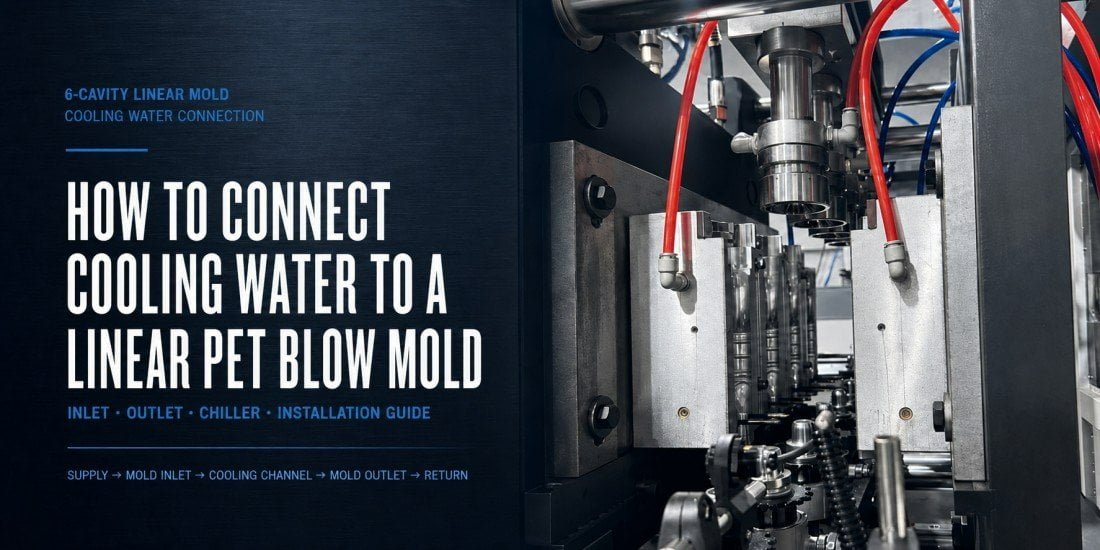
A linear PET blow mold is not ready for continuous production simply because it has been mechanically installed on the blow molding machine. The cooling circuit must also be connected correctly, checked for flow and leakage, and verified under machine movement.
A proper linear PET blow mold cooling connection continuously removes heat transferred from hot PET preforms into the mold, helping the tooling maintain a stable working temperature during repeated production cycles.
For replacement molds, cooling compatibility should be confirmed before manufacturing whenever possible. Machine brand and model data are useful, but they are not always enough. Hose arrangements, connector specifications, water circuits, and even the cooling connection method can differ between machines that appear to be the same model.
That is especially important when the mold is being shipped overseas.
Why Does a Linear PET Blow Mold Need Cooling Water?
During continuous stretch blow molding, reheated PET preforms repeatedly transfer heat into the mold cavity. Cooling water removes this accumulated heat so that the mold can remain within a stable operating condition and provide repeatable bottle cooling from one production cycle to the next.
The main heat entering the blow mold during production does not come from the opening and closing movement of the mold.
It comes primarily from the hot preform.
In a two-stage PET stretch blow molding process, the preform is reheated before entering the mold. It is then stretched and expanded against the mold cavity by pre-blow and high-pressure blowing.
During contact with the cavity surface, part of the thermal energy in the PET is transferred into the metal tooling.
One cycle transfers only a limited amount of heat. Continuous production is different.
When hot preforms enter the same mold repeatedly, cycle after cycle, heat continues to enter the mold. If the cooling circuit cannot remove that heat at a sufficient and stable rate, the mold temperature gradually increases.
The purpose of the cooling system can therefore be summarized as a continuous heat balance.
| Production Stage | What Happens Thermally | Why Cooling Matters |
|---|---|---|
| Reheated preform enters mold | Hot PET brings thermal energy into the cavity | The mold begins absorbing heat from the preform |
| Stretch and blowing occur | PET expands against the cavity and base surfaces | Large areas of hot material contact the tooling |
| Bottle is held in the mold | Heat transfers from PET into the mold | Bottle geometry begins to stabilize |
| Cooling water passes through mold channels | Heat is carried away from the tooling | Mold temperature is prevented from continuously increasing |
| Next preform enters | Another heat load is introduced | Stable cooling allows the process to repeat consistently |
The objective is not simply to make the mold feel cold to the hand.
The more important objective is to maintain a repeatable thermal condition.
If the mold becomes too hot for the application, the bottle may not receive consistent cooling before demolding. Depending on the bottle geometry, process condition, and severity of the thermal imbalance, this may contribute to dimensional instability, insufficient bottle definition, post-demolding deformation, or unstable continuous production.
If bottle deformation is already occurring, the mold temperature should be evaluated together with the blowing process rather than treated as the only possible cause. Our PET bottle deformation troubleshooting guide explains this broader diagnostic approach.
Cooling is therefore part of the forming process, not an optional accessory added after the mold is installed.
Where Does the Cooling Water for the Blow Mold Come From?
Cooling water may come from an integrated machine cooling arrangement or from an external chiller connected to the blow molding machine or mold circuit. The exact configuration depends on the machine and production line, so the customer should identify the existing cooling system before connecting a replacement mold.
Not every PET blow molding line uses the same cooling arrangement.
Some production lines already have a cooling-water distribution system incorporated into the equipment installation.
Others use a separate industrial chiller located beside or near the blowing machine.
The chiller may supply cooling water to the machine, and the machine then distributes it to the molds. In other installations, dedicated lines may connect the cooling supply more directly to specific tooling circuits.
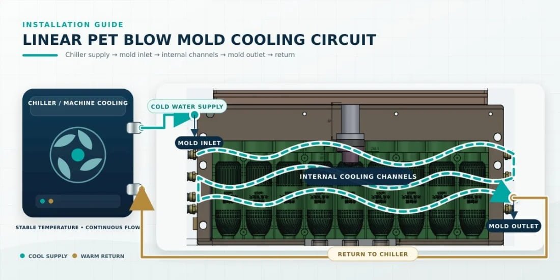
The general water path is similar even though the actual piping arrangement can differ.
| Cooling Stage | Function |
|---|---|
| Chiller or cooling-water supply | Removes heat from the circulating water |
| Machine-side supply line | Delivers cooled water toward the mold |
| Mold inlet | Introduces water into the designated mold cooling circuit |
| Internal cooling channels | Transfer heat from the mold metal into the water |
| Mold outlet | Allows heated return water to leave the mold |
| Return line | Sends the water back to the cooling system for heat removal |
This is why the first question during installation should not be:
“Which hose do I connect first?”
It should be:
“How is this particular blow molding machine designed to supply and return mold cooling water?”
Once that is clear, the mold connections can be matched to the machine correctly.
What Cooling Connections Should Be Confirmed Before the Blow Mold Is Shipped?
For a replacement linear PET blow mold, the cooling arrangement should be checked during the mold-design stage. Machine model information is useful, but actual connection photos, fitting specifications, hose arrangement, water-flow direction, and separate base-cooling requirements provide much stronger confirmation.
When we manufacture a mold for our own blow molding machine, we already control the machine interface and tooling standard.
Replacement molds are different.
The customer may be using another Chinese machine brand, a locally modified machine, or an older machine that has been changed during maintenance.
This is why we ask for more than a machine nameplate.
The basic information we normally want to confirm is shown below.
| Information to Confirm Before Manufacturing | Why We Need It |
|---|---|
| Blow molding machine brand and model | Establishes the general machine platform |
| Photos of the existing mold installed on the machine | Shows the real installation arrangement |
| Close-up photos of cooling connections | Confirms connector location and orientation |
| Connector or fitting specification | Helps the new mold match the customer’s existing hoses |
| Existing hose specification | Reduces the risk of requiring new hoses after delivery |
| Inlet and return-water arrangement | Confirms the intended cooling flow path |
| Number of independent cooling circuits | Prevents an incomplete connection plan |
| Whether the base mold has separate cooling | Confirms whether additional supply and return connections are required |
| Available clearance around fittings and hoses | Helps prevent interference with moving machine components |
| Photos during machine-open and machine-closed positions if needed | Helps evaluate hose movement and available space |
This checking process is particularly important for overseas replacement tooling.
A fitting that is inconvenient in our workshop may take minutes to replace.
A fitting that does not match after a mold has arrived in Oman, Thailand, Mexico, Saudi Arabia, or another overseas factory can delay installation and create unnecessary local modification work.
Case Study: Why We Rechecked the Cooling Connections for a 6-Cavity Mold in Oman
A recent Oman project shows why machine-model data should be verified against the customer’s actual equipment. The customer wanted one 6-cavity linear PET blow mold for a Chinese-brand machine. We already had technical data for that machine platform, but we still requested additional confirmation of the water connections and fitting details before starting the mold.
This was our first project with the customer.
It was also not one of our own blowing machines.
The customer was purchasing a 6-cavity linear PET blow mold for a Chinese-brand blow molding machine.
We already had data for that machine.
The customer therefore asked why we still needed so many details about the cooling-water connection, fitting type, and existing installation.
The reason is based on previous replacement-mold experience.
We have encountered machines with the same brand and the same nominal model where the actual cooling connection arrangement was not identical.
This can happen because the machine manufacturer has modified an individual machine, because a later production version uses a different arrangement, or because the end user’s maintenance team has changed hoses and connectors after the machine entered service.
The machine nameplate may remain the same.
The actual installation does not necessarily remain identical.
For that reason, our current approach for overseas replacement molds is to treat historical machine data as a reference rather than the final confirmation.
We still compare it with the customer’s actual machine.
| Available Information | How We Use It |
|---|---|
| Our existing data for the machine model | Starting reference for mold design |
| Customer’s current machine photos | Verification of the actual machine condition |
| Existing mold photos | Confirmation of real mounting and cooling arrangement |
| Water fitting details | Confirmation before machining and assembly |
| Hose layout | Check for compatibility and movement clearance |
| Inlet and return arrangement | Confirmation of the intended field installation |
This additional verification may seem repetitive at the quotation or design stage.
For overseas molds, however, the cost of checking one more photograph is very small compared with discovering an incompatible connection after the mold has been shipped internationally.
Cooling compatibility should be confirmed during mold design, not after the mold arrives at the customer’s factory.
The same principle applies to the broader mechanical interface. Our article Custom Blow Molds: 4 Reasons Your New Mold Won’t Fit Your Blowing Machine explains why machine model alone does not always guarantee replacement-mold compatibility.
How Do You Identify the Water Inlet and Outlet After Receiving the Mold?
The inlet and outlet should be identified from the mold markings, cooling-circuit drawing, or supplier installation information. Operators should not assume the flow direction from hose color, connector position, or whether a fitting is located on the left, right, upper, or lower side of the mold.
Once the mold arrives, the installer should first review the information supplied with the tooling.
If the mold has clearly marked IN and OUT connections, follow those markings.
If a cooling-circuit drawing is available, use the drawing.
If there are several circuits, confirm each circuit separately instead of assuming that all connectors form one continuous path.
This is particularly important when the main cavity and base mold use separate cooling arrangements.
Do Not Use Hose Color as an Industry Standard
A red hose may be used for supply water in one factory and return water in another.
A blue hose may mean return water on one machine but have no defined meaning at all on another.
Red hose does not automatically mean inlet, and blue hose does not automatically mean outlet.
Hose color is often a factory or machine-builder convention rather than a universal PET blow molding standard.
The same warning applies to connector position.
The left-side fitting is not automatically the inlet.
The lower fitting is not automatically the return.
If the information is unclear, contact the mold supplier before starting production.
A controlled water-flow check can be used as a verification method when necessary, but it should not replace proper installation documentation.
How Should You Connect the Cooling Hoses to a Linear PET Blow Mold?
After the mold has been correctly positioned and secured, connect the confirmed supply line to the designated inlet and the return line to the designated outlet. Then inspect the sealing, hose routing, bend radius, movement allowance, and machine clearance before automatic production begins.
The cooling connection should be treated as part of the mold installation sequence.
It should not be completed by simply attaching whichever hose happens to reach the fitting.
A practical installation sequence is shown below.
| Installation Step | What Should Be Confirmed |
|---|---|
| 1 | The mold has been correctly positioned and mechanically fixed |
| 2 | All cooling circuits and IN / OUT connections are identified |
| 3 | The correct connector and hose specifications are available |
| 4 | Supply and return hoses are connected to the intended ports |
| 5 | Sealing surfaces and O-rings are correctly installed where applicable |
| 6 | Hoses have sufficient length without unnecessary tension |
| 7 | Hose bends are smooth enough to avoid flow restriction |
| 8 | Machine movement is checked manually or at safe low speed |
| 9 | Hoses do not contact moving mechanisms or sharp edges |
| 10 | Cooling water is tested before continuous production begins |
Hose Length Matters
A cooling hose can appear acceptable when the machine is stopped but become too short when the mold opens.
Linear blow molding equipment operates with repeated mechanical movement.
The cooling hoses must therefore be checked through the entire movement cycle.
A hose should not become tight at the fully open position.
It should not be trapped when the mold closes.
It should not rub continuously against a moving plate, frame, guide, or other machine structure.
This is one reason installation should be inspected dynamically rather than only from a static photograph.
Avoid Excessive Hose Bending
If a hose is forced into a very tight bend because the connector direction is inconvenient, the internal flow area can become restricted.
The result may be reduced water flow even though the hose is technically connected.
A connection that does not leak is therefore not automatically a good cooling connection.
It must also allow sufficient and stable flow.
Check the Sealing Method
The correct sealing method depends on the connection design.
Where O-rings are used, they should be clean, correctly positioned, and undamaged.
Where a specific fitting or thread sealing method is required, the installation should follow that connection design rather than improvising a different sealing method on site.
During long-term production, cooling connections and seals should also be included in routine tooling inspection. Our PET Blow Mold Preventive Maintenance guide covers this type of preventive checking in more detail.
How Do You Check the Cooling Circuit Before Starting Continuous Production?
After the hoses are connected, start the cooling circuit before high-speed production and verify that water can enter and return normally. Check all connections for leakage, compare mold temperatures where possible, and confirm that every mold position receives effective cooling rather than relying only on the main system pressure.
One of the most important points on a multi-cavity linear blow molder is that system pressure alone does not prove that every mold circuit has sufficient flow.
A main water line may show normal pressure while one branch is partially restricted.
For example, one hose may be bent, one connector may have a smaller effective passage, or one mold circuit may contain contamination or blockage.
That can leave one mold position hotter than the others.
The initial cooling check should therefore combine visual inspection with comparison between positions.
| Pre-Production Check | What a Normal Result Should Suggest | If the Result Is Abnormal |
|---|---|---|
| Supply line connected | Water reaches the intended mold circuit | Check valves, hose routing, and supply system |
| Return line active | Water is circulating through the circuit | Check for blockage or incorrect connection |
| Connections remain dry | Seals and fittings are holding | Locate the first leakage point |
| Hose remains open and unpinched | Flow path is mechanically unrestricted | Re-route or replace the hose |
| Similar mold positions cool consistently | Cooling distribution is reasonably balanced | Investigate the hotter position separately |
| Base mold cooling operates if independently connected | Complete tooling cooling is active | Check the separate base circuit |
| Cooling remains stable during machine motion | Hose movement is acceptable | Correct tension, bending, or interference before production |
Start With Cooling Before High-Speed Production
There is little value in immediately running the machine at production speed before the cooling system has been checked.
A better sequence is to establish the cooling circuit first, inspect the connections, and then begin a controlled production trial.
During the trial, monitor whether the mold temperature appears stable and whether the bottles remain dimensionally consistent.
The production team should also compare different mold positions.
If all positions gradually become too hot, the problem is more likely related to the overall cooling supply, chiller condition, temperature, or total flow.
If only one position is abnormal, the diagnosis should move toward that individual branch, hose, fitting, or internal mold circuit.
What Are the Most Common Cooling-Hose Installation Mistakes?
Most field problems are not caused by complicated cooling-channel failures. Incorrect hose routing, incompatible fittings, poor sealing, insufficient hose length, restricted bends, or failure to check the full machine movement can all create cooling or leakage problems after a new mold is installed.
The following table summarizes common installation problems and the most useful first response.
| Installation Problem | Possible Result | Recommended Direction |
|---|---|---|
| Hose is sharply bent | Restricted cooling-water flow | Re-route the hose with a smoother bend |
| Connector specification does not match | Poor installation or leakage | Use the correct compatible fitting |
| Seal is damaged or incorrectly installed | Water leakage around the connection | Inspect and replace the appropriate seal |
| Hose is too short | Hose becomes tight during mold movement | Increase hose length or change routing |
| Hose is excessively long and uncontrolled | Hose may contact moving equipment | Secure and route the hose correctly |
| Connector points toward a moving component | Mechanical interference during operation | Change fitting orientation if the design allows |
| One mold branch has weak flow | Uneven cooling between mold positions | Check that branch independently |
| Base cooling circuit is not connected | Incomplete cooling of the tooling | Confirm whether the base requires a separate circuit |
| Installer assumes hose color determines flow direction | Inlet and return may be connected incorrectly | Follow markings or supplier documentation |
| Mold surface develops large amounts of water | Could be leakage or condensation | Identify the actual water source before repairing the mold |
Water on the Mold Does Not Always Mean Leakage
A wet mold surface can create another installation misunderstanding.
Cooling water may genuinely be leaking from a connector or seal.
However, a cold mold operating in a warm and humid environment can also develop condensation.
In that case, water is forming from moisture in the air rather than escaping from the cooling circuit.
This is why the installer should locate the true water source rather than immediately dismantling a new mold.
If the entire mold surface gradually develops fine droplets without one clear leakage point, cooling-water temperature and local humidity should also be evaluated.
What Should You Do If the Mold Is Still Too Hot After the Cooling Water Is Connected?
If the mold remains too hot during continuous production, troubleshoot the complete cooling path instead of immediately blaming the mold. First determine whether all mold positions are hot or whether only one circuit is abnormal, then check supply temperature, available flow, hose restrictions, fittings, and internal cooling passages.
A connected hose does not automatically mean that the mold is receiving effective cooling.
The diagnosis should begin at the system level.
If All Mold Positions Are Too Hot
When every mold position shows a similar temperature problem, first investigate the common cooling conditions.
This may include:
- whether the chiller or central cooling system is operating normally;
- whether the available cooling-water temperature is suitable for the process;
- whether total water flow is sufficient for the installed tooling;
- whether supply and return lines are restricted;
- whether valves are correctly positioned.
A common problem across all molds usually points toward something shared by all of them.
If Only One Mold Position Is Too Hot
A single abnormal position requires a different approach.
Compare it with neighboring positions operating under the same production conditions.
Then inspect the local hose, connection, flow path, and mold circuit.
| Temperature Pattern | More Likely Investigation Direction |
|---|---|
| All mold positions run hotter than expected | Overall chiller, supply temperature, total flow, or system capacity |
| Only one mold position is hot | Local hose, connector, branch flow, or internal circuit |
| Main cavity is acceptable but bottle base area remains too hot | Check whether the base has a separate cooling circuit |
| Temperature changes when the machine opens or closes | Inspect hose tension, kinking, or movement interference |
| Cooling is good initially but gradually deteriorates | Check system stability, flow restriction, or heat-removal capacity |
| One repaired or replaced hose causes a new temperature difference | Compare its internal diameter, fitting restriction, and routing with the original |
Internal cooling passages should normally be investigated only after easier external causes have been checked.
This prevents unnecessary mold dismantling.
If an internal passage is suspected, the mold supplier can help determine whether controlled flow testing, cleaning, or further inspection is appropriate.
Why Is Cooling Compatibility Especially Important for Overseas Replacement Molds?
For an overseas replacement mold, a cooling-interface mistake creates a much larger service problem than it would inside the mold manufacturer’s factory. Confirming the actual machine before manufacturing helps reduce local modifications, installation delays, and unnecessary international shipment of mold components.
Replacement mold projects always involve an interface between two manufacturers.
The blow molding machine may come from one company.
The new mold may come from another.
Both designs have to meet correctly at the customer’s factory.
This is why we do not consider a machine model number sufficient confirmation for every replacement project.
Historical technical data is valuable.
It allows us to understand the general machine platform and begin engineering more efficiently.
However, actual customer photos remain important because machines may have been modified.
Our Oman 6-cavity project is a good example.
We already had information for the Chinese machine brand, but we still confirmed the customer’s actual water arrangement and connector details before opening the mold design for production.
The customer initially wondered why so much confirmation was necessary.
From our perspective, the answer is simple:
overseas tooling leaves very little room for assumptions.
A small mismatch can mean that the customer cannot connect the mold on the day it arrives.
A few additional checks before manufacturing can prevent that situation.
This same principle is discussed from a wider commissioning perspective in The Commissioning Trap: Why Your First Blow Mold Should Come From Your Machine Supplier. Replacement tooling requires careful confirmation because the mold supplier does not control every detail of the customer’s machine.
What Information Should You Send When Ordering a Replacement Linear PET Blow Mold?
For a replacement mold, the most useful information is not only the bottle drawing. The mold manufacturer also needs enough machine-side data to reproduce the mechanical and cooling interfaces accurately, especially when the new tooling will be installed overseas without the mold manufacturer present.
The amount of information required depends on the machine and project, but the following package is useful for many linear replacement-mold orders.
| Information | Why It Matters |
|---|---|
| Bottle drawing or approved sample | Defines the required cavity geometry |
| Machine brand and model | Establishes the general platform |
| Existing mold photos | Shows the real installation arrangement |
| Mold mounting dimensions | Confirms mechanical compatibility |
| Cavity number | Defines the mold-set configuration |
| Cavity pitch where applicable | Confirms machine spacing |
| Cooling connector photos | Shows the actual field connection |
| Connector specification | Helps match the customer’s existing water lines |
| Supply and return arrangement | Confirms the cooling flow path |
| Separate base-cooling details | Prevents missing circuits |
| Photos of hoses during machine movement if needed | Helps verify movement allowance |
| Existing mold drawing if available | Provides an additional engineering reference |
The exact list should not be treated as paperwork for its own sake.
Every useful item reduces uncertainty before machining begins.
For overseas customers, that is particularly valuable because many installation problems are much easier to prevent than to correct after delivery.
FAQ
Why Does a PET Blow Mold Need Cooling Water?
A reheated PET preform transfers heat into the blow mold during every forming cycle.
During continuous production, this heat accumulates unless it is removed.
Cooling water carries heat away from the mold and helps maintain a stable tooling temperature so that bottles can cool and form more consistently before demolding.
Does the Cooling Water Come From the Blow Molding Machine or a Separate Chiller?
Either arrangement is possible.
Some production lines have an integrated cooling-water distribution system, while others use an external chiller connected to the machine or tooling circuits.
The correct installation depends on the actual blow molding machine and factory cooling arrangement.
How Do I Know Which Hose Is the Inlet and Which Is the Outlet?
Use the IN / OUT markings on the mold, the cooling-circuit drawing, or the mold supplier’s installation information.
Do not identify flow direction only from hose color, fitting position, or whether the connector is on the left or right side.
If the information is unclear, confirm it with the mold supplier before production.
Can I Connect a New PET Blow Mold Directly to My Existing Cooling Hoses?
Only after compatibility has been confirmed.
The connector specification, hose size, sealing method, cooling-circuit arrangement, hose length, and movement clearance should all match the installation requirements.
For a replacement mold, these details are best confirmed before manufacturing rather than after shipment.
Why Is My PET Blow Mold Still Hot Even Though Cooling Water Is Connected?
A connected circuit may still have insufficient effective flow.
Check whether all mold positions are hot or only one is abnormal.
Then inspect the cooling-water supply, hose routing, bends, fittings, local branch flow, separate base circuit if applicable, and finally the internal mold passages if external causes have been eliminated.
Conclusion
Installing a linear PET blow mold involves more than mechanically fixing the tooling into the machine.
The cooling circuit is part of the installation.
Hot PET preforms continuously transfer heat into the mold during production. The cooling-water system must remove that heat at a stable rate so that the tooling does not continue to rise in temperature from cycle to cycle.
For a new or replacement mold, the correct sequence is straightforward:
first understand where the machine’s cooling water comes from, confirm the actual cooling connections, identify the mold inlet and outlet, install the hoses without restriction or movement interference, test the circuit, and only then move into continuous bottle production.
For overseas replacement tooling, we also recommend confirming the actual machine rather than relying only on historical model data.
Our recent 6-cavity project in Oman illustrates why.
Although we already had technical information for the customer’s Chinese blow molding machine, we still checked the current cooling connections and fitting details because machines with the same brand and model can sometimes have different field configurations.
That extra confirmation is part of reducing installation risk before the mold leaves our factory.
A blow mold is not fully installed when it is only bolted into the machine. Cooling must also be connected, verified, and stable before continuous bottle production begins.
If you are ordering a replacement linear PET blow mold, you can send us your bottle drawing or sample, machine brand and model, existing mold photos, cooling-connection close-ups, connector specifications, cavity number, cavity pitch where applicable, and base-cooling arrangement. We can compare these details before manufacturing so that the new mold is prepared for the actual machine installed in your factory.
Related PETMOLDER Articles
- Semi-Auto vs. Fully Auto PET Blow Molds and Mechanical Compatibility
- Custom Blow Molds: 4 Reasons Your New Mold Won’t Fit Your Blowing Machine
- The Commissioning Trap: Why Your First Blow Mold Should Come From Your Machine Supplier
- PET Blow Mold Preventive Maintenance: A Complete Guide for Aluminum and Stainless Steel Tooling
- Comprehensive Troubleshooting: Why Do PET Bottles Deform After Blowing and How to Fix Them