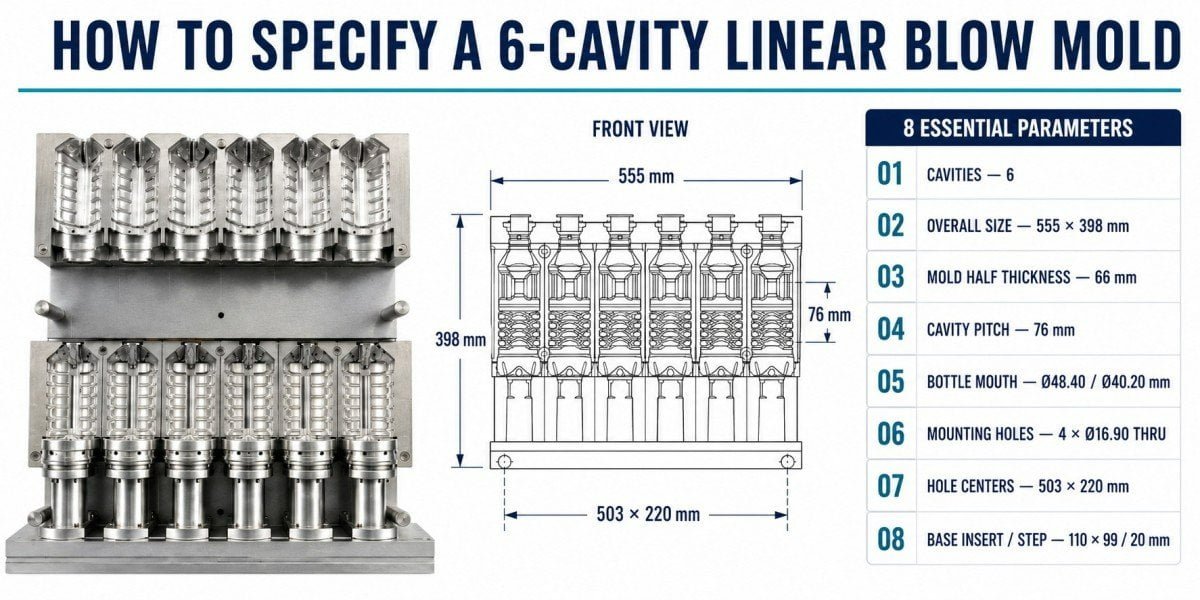
To specify a 6-cavity linear blow mold correctly, the mold supplier needs more than the bottle drawing and blow molding machine model. The mold envelope, cavity pitch, neck and preform interface, mounting layout, cooling circuit, water connections, bottom mold interface, and material specification should all be confirmed against the actual machine before manufacturing begins.
This is particularly important for replacement molds.
A customer may already own a six-cavity PET blow molding machine and may even have the original machine manual. That information is valuable, but it does not always prove that every interface on the machine currently installed in the factory is identical to the standard machine data.
We encountered exactly this situation with a beverage customer in Vietnam.
Real Project: Why We Rechecked a Vietnamese Customer’s Machine Even Though We Already Had Machine Data
The customer wanted to order a 6-cavity linear PET blow mold for a Chinese-brand blow molding machine.
He already had general machine information, and we were also familiar with the machine platform. From the customer’s perspective, this created a reasonable question:
If the machine brand and model are already known, why do we still need photographs, interface dimensions, cooling-connection details, and information from the existing mold?
Our answer was that machine-model data is the starting reference, not always the final manufacturing reference.
During replacement-mold projects, we have encountered equipment from the same manufacturer and nominal model family with differences caused by production-year revisions, optional configurations, machine-builder modifications, or later changes made at the customer’s factory.
A new mold is not installed into a catalogue.
It is installed into the actual machine standing on the customer’s production floor.
For this Vietnamese project, we therefore verified the important mechanical and cooling interfaces against the customer’s real equipment before releasing the mold for manufacturing.
| Information Available at the Start | Why We Still Verified the Actual Machine |
|---|---|
| Machine brand and model | Establishes the general linear blow molding platform but may not capture every machine revision |
| General machine manual | Provides useful dimensional references but may not show later modifications |
| Existing PET bottle information | Defines the package but does not define the mold-to-machine interface |
| Historical tooling data | Helps begin mold design but should be compared with the customer’s current installation |
| Actual machine and existing mold photos | Show how the tooling is mounted, cooled, and connected in the factory |
| Customer-confirmed interface dimensions | Reduce the risk of discovering a mechanical mismatch after international shipment |
This is the main reason we recommend confirming eight areas before a 6-cavity linear mold is machined.
| Specification Area | Main Question Before Mold Manufacturing |
|---|---|
| 1. Mold envelope and closed thickness | Will the complete mold physically fit and close correctly in this machine? |
| 2. Cavity pitch | Do all six cavity centerlines correspond to the machine’s blow-station and transfer positions? |
| 3. Neck and preform interface | Can the machine, preform, and mold work together around the neck/support-ring area? |
| 4. Mounting and locating layout | Can the mold be installed in the correct position without field modification? |
| 5. Cooling circuit | Can heat be removed consistently across all six cavities? |
| 6. Water connections | Can the mold connect directly to the customer’s actual cooling supply without hose interference? |
| 7. Bottom mold interface | Does the base mold match the machine’s lifting, locating, and operating arrangement? |
| 8. Mold material | Does the selected material suit production, cooling, maintenance, and budget requirements? |
The objective is not to collect more dimensions than necessary.
The objective is to remove uncertainty before CNC machining.
For overseas replacement molds, that distinction matters because correcting one interface in our Guangdong factory is relatively simple. Correcting the same interface after a complete 6-cavity mold has arrived at the customer’s factory can require local machining, additional parts, production delays, and another round of commissioning.
Machine compatibility should be confirmed before the mold ships, not discovered during installation.
1. What Overall Mold Dimensions and Closed Thickness Must Be Confirmed?
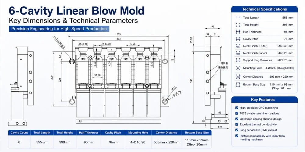
The complete mold envelope and closed thickness must fit the actual mold carrier and closing mechanism of the linear blow molding machine. A bottle cavity can be perfectly machined and still be unusable if the mold block is too large, too thick, or incompatible with the available installation and opening space.
The first specification is the physical envelope of the tooling.
A 6-cavity mold is not simply six single cavities placed next to each other. The complete assembly also includes the surrounding mold body, cooling channels, mounting features, locating structures, connection areas, and the space required for the bottom mold arrangement.
The machine has its own physical limits.
For this reason, the supplier should confirm the actual installation envelope rather than design only from the bottle diameter.
The important dimensions depend on the machine platform, but the engineering review generally includes the overall mold length, height, closed thickness, available opening space, and any machine structures that can interfere with the tooling.
Why Closed Thickness Matters
The two cavity halves have to close in the position intended by the machine.
If the complete mold stack is not compatible with the machine’s closing geometry, the problem cannot be solved simply by changing the bottle cavity.
A mold that is too thick may prevent the closing mechanism from reaching its intended operating position. A mold that is too thin may require a correctly engineered mounting or spacer arrangement if the machine design permits it.
The actual solution depends on the machine.
This is why we do not recommend taking one closed-thickness dimension from another six-cavity machine and treating it as a standard.
| Dimension to Verify | Why It Matters |
|---|---|
| Overall mold length | Must fit the available horizontal mold-carrier space |
| Overall mold height | Must remain clear of surrounding machine structures and mechanisms |
| Closed mold thickness | Must work with the machine’s closing and locking arrangement |
| Available mold-opening distance | Must allow the finished bottle to release without interference |
| Clearance around fittings and mounting hardware | Prevents collision with machine structures during operation |
| Available bottom mold space | Allows the base mold and its mechanism to operate correctly |
This is also why existing mold photographs can be extremely useful.
If the customer already has a mold running on the same machine, the old mold provides direct evidence of the machine interface.
We can compare its external dimensions and mounting arrangement with the proposed new tooling rather than relying only on generic machine information.
Our article Custom Blow Molds: 4 Reasons Your New Mold Won’t Fit Your Blowing Machine explains this replacement-tooling problem in more detail.
2. Why Is Cavity Pitch Critical on a 6-Cavity Linear Blow Mold?
Cavity pitch is the center-to-center distance between neighboring bottle positions, and it must correspond to the actual blowing station and preform-transfer arrangement of the machine. On a six-cavity system, the pitch controls the position of every cavity across the complete mold, so it should never be selected only from bottle diameter.
This is one of the most important dimensions on a multi-cavity linear mold.
The six cavities are not positioned independently.
They have to correspond to six preform positions created by the machine.
When heated preforms are transferred into the blowing station, their centerlines need to align with the cavity centerlines and the related stretching/blowing components.
The machine architecture therefore determines the required pitch.
Why a Six-Cavity Mold Makes Pitch Verification More Important
On a single-cavity mold, one centerline has to match the machine.
On a six-cavity mold, the complete pattern has to match.
If the pitch is wrong, the error affects the relationship between neighboring stations across the mold.
This is why we want the machine pitch confirmed directly rather than estimated from a photograph or calculated only from the outside width of an existing mold.
| Pitch-Related Information | What It Confirms |
|---|---|
| Machine blow-station pitch | Defines the required cavity center spacing |
| Existing mold cavity pitch | Provides direct field evidence from tooling already running on the machine |
| Preform transfer spacing | Confirms that the transferred preforms arrive at the intended cavity positions |
| Bottle maximum diameter | Determines whether the proposed bottle can physically fit within the available pitch |
| Required spacing between cavities | Provides material for mold structure, cooling, and mechanical strength |
Bottle diameter and cavity pitch should also be reviewed together.
Suppose the customer wants to move from a relatively narrow water bottle to a much wider container.
Even if the machine has six blowing stations, the existing pitch may not provide enough space for six molds of the new diameter.
This is especially relevant when customers expand into wide-mouth jars or other large-diameter packaging.
A machine described as “6 cavity” therefore tells us the number of stations.
It does not tell us every bottle format those six stations can accommodate.
The broader distinction between machine types and tooling interfaces is discussed in Semi-Auto vs. Fully Auto PET Blow Molds and Mechanical Compatibility.
3. What Neck Finish and Preform Interface Information Is Required?
The supplier should confirm the exact neck finish, support-ring geometry, preform dimensions, and the way the machine carries and locates the preform. A neck standard name alone may not provide enough information to manufacture every machine-side clearance correctly, particularly when the mold is being supplied as replacement tooling.
The neck area requires more careful terminology than simply saying that the blow mold “clamps the thread.”
In two-stage PET stretch blow molding, the thread and neck finish have already been formed during preform injection molding and are generally protected from the main reheating and stretching process.
The blow molding machine transports and locates the preform through its neck/support-ring arrangement, while the blow nozzle and surrounding tooling must also be compatible with the neck system.
The blow mold therefore needs appropriate clearance and geometry around this interface.
A Neck Name Is Useful, but a Drawing Is Better
A customer may tell us that the project uses PCO 1881, 30/25, 28/410, or another neck finish.
That information immediately narrows the engineering direction.
However, when replacement tooling is being manufactured for equipment supplied by another machine company, we still prefer the actual preform drawing or approved sample where possible.
| Neck/Preform Information | Why We Request It |
|---|---|
| Neck finish specification | Defines the closure and functional neck geometry |
| Preform drawing | Provides actual support-ring, neck, and body dimensions |
| Physical preform sample where available | Allows the tooling team to cross-check the real production part |
| Preform weight | Provides context for the bottle project and material distribution |
| Support-ring geometry | Relevant to machine handling and mold clearance |
| Existing mold neck-area photos | Show how the customer’s current tooling interfaces with the machine |
| Machine handling information | Confirms how the preform is transferred and located |
This information also protects the neck from an incorrect mold interface.
The objective is not to make the clearance “as tight as possible.”
The objective is to provide the correct relationship between the actual preform, mold, blow nozzle, and machine handling system.
If the neck region is specified incorrectly, installation or production problems can appear even when the bottle body cavity itself is correct.
For buyers working with different PET neck systems, The Ultimate Guide to Preform Neck Finishes explains why the nominal neck diameter alone is not enough to define the complete interface.
4. How Should the Mounting and Locating Layout Be Specified?
Mounting holes, clamp surfaces, locating features, and their coordinates should match the actual machine carrier. The mold must not only be physically attached to the machine; it must also sit in the correct repeatable position relative to the preform, stretch system, bottom mold, and opposite mold half.
A mounting hole is not just a hole for a bolt.
The complete mounting layout defines how the tooling sits on the machine.
Different machine builders use different arrangements. Some tooling is directly bolted. Other systems use clamp surfaces, locating blocks, quick-change arrangements, or combinations of several features.
This means an existing drawing from another machine cannot automatically be reused.
Mounting and Positioning Are Related but Not Identical
Fasteners hold the mold in place.
Locating features establish where it should be.
Both functions need to be understood.
A mold could theoretically be bolted onto a carrier while still sitting in the wrong relationship to the machine centerline.
For a six-cavity system, that positional error would influence the relationship across all six stations.
| Mounting Information | Engineering Purpose |
|---|---|
| Hole diameter and thread/through-hole arrangement | Confirms the correct fastening method |
| Horizontal and vertical hole coordinates | Matches the actual machine carrier |
| Locating surface or locating feature | Establishes repeatable mold position |
| Clamp-edge geometry where used | Confirms that machine clamps can engage correctly |
| Mounting-face thickness | Influences the final cavity position in the machine |
| Clearance around bolts and clamps | Prevents interference during mold installation and operation |
For an overseas replacement mold, we prefer to compare at least two references whenever possible: the machine information and the customer’s existing mold.
If the two disagree, that disagreement should be resolved before machining.
It should not be discovered after shipment.
This is closely related to the commissioning risk discussed in The Commissioning Trap: Why Your First Blow Mold Should Come From Your Machine Supplier. When tooling is supplied by a different manufacturer from the blow molding machine, interface verification becomes an important part of the mold project.
5. What Should Be Confirmed About the Cooling Circuit?
A 6-cavity linear mold needs a cooling layout that removes heat consistently from all bottle positions during continuous production. The specification should therefore consider the actual cavity geometry, water-flow arrangement, separate base cooling where applicable, and how the machine supplies and returns cooling water.
Every heated PET preform transfers heat into the blow mold.
During continuous production, this thermal load repeats cycle after cycle.
The cooling system has to remove that heat so the tooling can maintain a reasonably stable operating condition.
The objective is not simply to make the aluminum feel cold.
The objective is consistent bottle cooling across all six cavities.
Why Multi-Cavity Cooling Needs More Than One Inlet and One Outlet on a Drawing
A cooling circuit can be connected and still perform poorly.
If one branch has significantly more flow resistance than another, or if a hose is restricted, the resulting mold temperature can vary between positions.
For this reason, cooling needs to be evaluated as a flow path.
| Cooling Question | Why It Should Be Confirmed |
|---|---|
| How are the six cavity areas cooled? | Helps maintain repeatable heat removal across the mold |
| Does the base mold have a separate cooling circuit? | Prevents the bottom tooling from being omitted from the cooling plan |
| How many machine-side water circuits are available? | The mold design must match the actual cooling supply arrangement |
| Where are the supply and return connections located? | Determines practical hose routing |
| Can each branch receive adequate flow? | Main-line pressure alone does not prove balanced cooling |
| Can the circuit be cleaned or serviced? | Long-term scale or contamination can reduce cooling performance |
The cooling channel design should follow the actual mold geometry.
We do not recommend specifying “conformal cooling” as a marketing term simply because the mold has six cavities.
Different blow mold designs use different drilled, connected, or machined water passages depending on the available material and geometry.
What matters is whether the system can remove heat effectively and consistently without compromising the mold structure.
If the customer already has a stable mold running on the same machine, its cooling arrangement is valuable reference information.
The new tooling can then be designed around the existing water supply rather than forcing the customer to rebuild the machine-side cooling system unnecessarily.
6. Why Must the Water Connector Type and Hose Arrangement Be Confirmed?
The cooling circuit is only useful if it can connect correctly to the customer’s machine. Connector thread, quick-coupling type, inlet/outlet location, hose diameter, and movement clearance should therefore be confirmed before shipment, especially when the mold is being installed on a machine supplied by another manufacturer.
This is one of the smallest details in the mold project and one of the easiest to underestimate.
A customer may receive a mechanically correct six-cavity mold and still be unable to start production because the new water fitting does not connect to the existing hoses.
That problem is usually inexpensive to correct inside our factory.
It becomes inconvenient after international shipment.
Connector Compatibility Is More Than Thread Size
The connection needs to fit physically and function during machine movement.
A correct thread with a fitting pointing in the wrong direction can interfere with a machine structure.
A hose that connects while the mold is stationary can become stretched or folded when the machine opens.
This is why we prefer actual installation photographs.
| Cooling-Connection Detail | What Needs to Be Verified |
|---|---|
| Connector thread/interface | Must match the approved fitting arrangement |
| Quick-coupling type if used | Should be compatible with the customer’s existing system |
| Supply and return identification | Prevents field guessing about the intended circuit |
| Connector orientation | Must remain clear of the machine structure |
| Hose length | Needs sufficient movement allowance |
| Hose bend radius | Should not create severe restriction |
| Machine movement | Hose must not be pulled, pinched, or trapped during a complete cycle |
We do not treat hose color as a universal standard.
A red hose on one machine can represent something different on another. The correct reference is the actual cooling drawing, IN/OUT marking, or confirmed machine installation.
This small detail is also a good example of why we asked our Vietnamese customer for more information even though the general machine data was already available.
The machine model told us the platform.
The customer’s real connection told us what the mold needed when it arrived at his factory.
7. What Bottom Mold Interface and Movement Data Must Be Confirmed?
The bottom mold must match the machine’s base-mold mounting, locating, movement, and available stroke. Its relationship with the side cavities and stretch system should also be verified so the bottle base closes correctly, releases correctly, and operates without mechanical interference.
The bottom mold is not simply a removable insert below the bottle.
On many linear machines, it operates as a separate moving component relative to the two side mold halves.
Its final working position contributes directly to the bottle base geometry.
The machine therefore defines part of the bottom mold interface.
Why Copying Only the Bottle Base Geometry Is Not Enough
A customer may provide a finished bottle drawing with a complete bottom design.
That drawing defines what the PET bottle should look like.
It does not define how the customer’s blow molding machine supports and moves the bottom mold.
The supplier still needs machine-side information.
| Bottom Mold Parameter | Why It Matters |
|---|---|
| Mounting footprint | Must fit the machine’s base-mold carrier |
| Locating geometry | Establishes repeatable position relative to the side cavities |
| Installed height | Determines the final relationship with the cavity |
| Available movement/stroke | Must permit correct closing and bottle release |
| Side mold-to-base mold transition | Needs geometric continuity in the closed position |
| Stretch-rod clearance/bottom position | Prevents conflict between the machine stretch system and tooling |
| Cooling connection if separate | Ensures the bottle base receives the intended thermal control |
The actual tolerances and positions should follow the machine design.
We do not recommend taking one bottom-mold dimension from another six-cavity platform and treating it as a standard specification.
Bottle Base Problems Are Not Always Mold-Interface Problems
If a new bottle later shows an off-center gate or base-forming problem, the bottom mold is only one area to inspect.
Preform centering, stretch-rod alignment, machine positioning, heating, and the blowing process can also influence the result.
For that reason, the bottom mold interface should be verified mechanically during design, while bottle defects should still be diagnosed from the complete process.
Our Bottom Gate Off-Center? A 6-Step Protocol to Fix PET Bottle Eccentricity explains this distinction in more detail.
8. How Should Material and Surface Treatment Be Specified?
A six-cavity mold does not automatically require one universal aluminum grade or surface treatment. Material should be selected according to the customer’s production conditions, mold structure, cooling requirement, wear areas, maintenance strategy, and budget, while different components may reasonably use different materials.
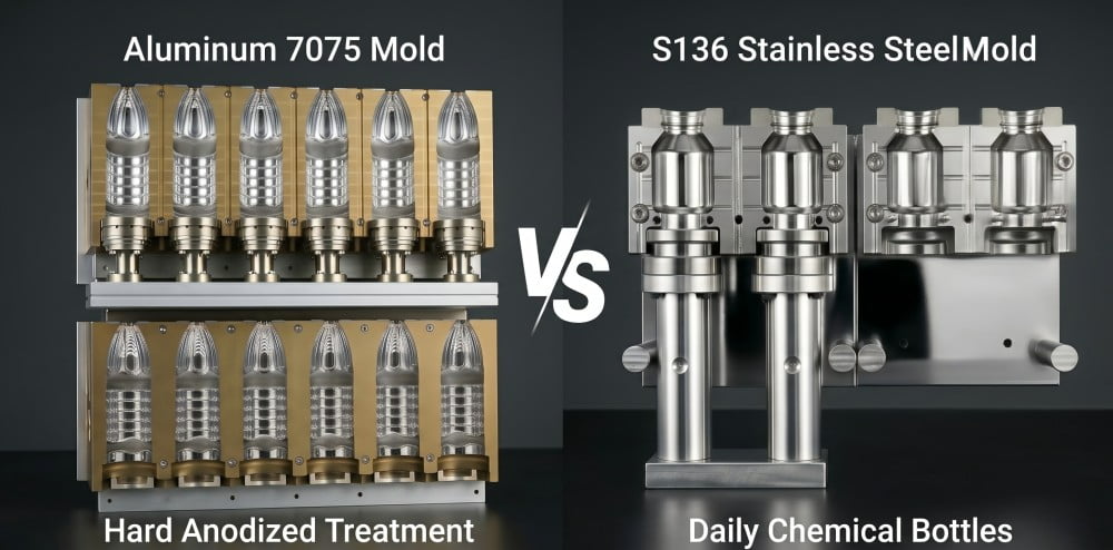
The original version of this article treated 7075 aluminum as if it were the only correct material for a six-cavity linear mold.
That is too broad.
High-strength aluminum alloys are widely used for PET blow mold cavity bodies because they combine machinability, relatively low weight, and useful heat-transfer performance.
However, the correct choice depends on the project.
Different manufacturers can use 7075, 6061, other aluminum grades, stainless steel, or different material combinations according to the tooling structure and production requirement.
Different Mold Components Can Have Different Priorities
The main cavity body and a wear-sensitive insert do not necessarily need the same material.
The cavity body benefits strongly from efficient machining and heat transfer.
Other locations may place more emphasis on wear resistance, corrosion resistance, dimensional stability, or serviceability.
| Component/Requirement | Material Selection Question |
|---|---|
| Main cavity halves | What balance of heat transfer, weight, machinability, and strength is required? |
| Bottom mold | Does the bottle base and machine arrangement require a different material or treatment? |
| Locating/wear components | Is greater local wear resistance required? |
| High-contact mounting areas | Should local inserts or harder materials be considered? |
| Surface treatment | Is anodizing or another treatment appropriate for the selected alloy and application? |
| Repair strategy | Can the chosen material be maintained or locally repaired in the customer’s market? |
Surface treatment should also be specified according to the actual alloy and application rather than copied automatically from another mold.
Different aluminum alloys can respond differently to anodizing and other treatments. Our article Why Are Most PET Blow Molds Made of Aluminum? 4 Engineering Reasons Explained provides more background on why aluminum is widely used, while Aluminum vs. Steel Blow Molds: How to Choose the Right Material covers the broader material-selection decision.
For a 6-cavity replacement mold, material specification should come after the mechanical compatibility review, not replace it.
A high-grade aluminum mold that does not fit the machine is still the wrong mold.
What Should You Send the Mold Supplier Before a 6-Cavity Linear Mold Is Manufactured?
The eight areas above can be converted into a practical project-information package.
The buyer does not necessarily need to create a new engineering drawing for every interface.
Good existing-mold photographs, machine information, physical samples, and supplier-to-customer measurement confirmation can often provide the required data efficiently.
| Information From the Customer | What We Use It For |
|---|---|
| Bottle 2D/3D drawing or approved sample | Defines the final cavity geometry |
| Target bottle volume and application | Provides packaging and performance context |
| Preform drawing, sample, and weight | Supports neck interface and stretch evaluation |
| Neck finish | Confirms closure and machine-handling compatibility |
| Blow molding machine brand and exact model | Establishes the general tooling platform |
| Machine nameplate photo | Helps confirm the specific installed machine |
| Existing 6-cavity mold photos | Shows actual mounting, cooling, and interface conditions |
| Existing mold external dimensions | Provides direct compatibility reference |
| Cavity pitch | Confirms all six blowing centerlines |
| Mounting and locating dimensions | Defines the machine-to-mold interface |
| Bottom mold dimensions/interface | Confirms machine base mechanism compatibility |
| Cooling connector close-ups | Allows fitting and hose arrangement to be prepared before shipment |
| Required production output | Provides context for cooling and production expectations |
This is the type of information we wanted to confirm in the Vietnamese project.
The customer initially viewed some of these questions as repetitive because the machine model was already known.
From our side, the additional verification had a specific purpose.
We were not trying to collect more data than necessary.
We were trying to avoid making an overseas replacement mold from assumptions that could be checked before CNC machining.
Why Existing Mold Photos Are Often Extremely Valuable
For replacement tooling, an existing mold that already operates correctly on the machine can be one of the strongest references available.
A clear set of photographs can show the actual cooling fitting orientation, mounting style, bottom mold arrangement, available hose space, and surrounding machine structures.
Dimensioned photographs are not a substitute for proper measurement, but they can help the tooling engineer identify which measurements are important.
This makes communication more efficient.
Instead of sending the customer a generic request for “all machine dimensions,” we can ask for the specific interface needed for the proposed mold.
Frequently Asked Questions
Is the Blow Molding Machine Model Enough to Manufacture a 6-Cavity Replacement Mold?
Usually, we do not recommend relying on the model number alone.
The machine model is a very important starting reference, but different production years, optional configurations, machine-builder revisions, and later factory modifications can change individual interfaces.
For overseas replacement tooling, the safest approach is to compare the available machine data with the customer’s actual machine and existing mold before manufacturing.
Why Is Cavity Pitch So Important on a 6-Cavity Linear Blow Mold?
The six cavity centerlines have to correspond to the machine’s six blowing positions and preform-transfer arrangement.
If the pitch is incorrect, the cavities cannot align correctly with the machine’s preform and stretching positions.
Pitch should therefore be confirmed from the machine or an approved existing mold rather than selected only from bottle diameter.
Can I Send Only the Bottle Drawing and Let the Mold Supplier Determine the Rest?
A bottle drawing defines the container geometry but does not fully define the machine interface.
For a replacement mold, the supplier also needs enough information to confirm the mold envelope, pitch, neck/preform interface, mounting system, cooling connections, and bottom mold arrangement.
The exact amount of additional information depends on the machine.
Do All 6-Cavity Linear Blow Molds Use 7075 Aluminum?
No.
7075 is one option used in PET blow mold manufacturing, but cavity count alone does not determine the correct alloy.
Material selection should consider the mold structure, production requirement, thermal performance, wear conditions, surface treatment, repair strategy, and customer budget.
Different mold components may also use different materials.
Why Do You Ask for Existing Mold and Cooling-Connection Photos if You Already Know My Machine Brand?
Because the actual machine installed in the customer’s factory is the final reference.
Existing tooling and connection photographs can reveal machine revisions, different fittings, modified hose arrangements, or installation details that may not appear in standard machine data.
For an overseas mold, confirming those details before manufacturing is usually much easier than correcting them after delivery.
Conclusion
A 6-cavity linear blow mold should not be specified as six bottle cavities inside a block of aluminum.
It is a machine-specific tooling system.
The bottle geometry must work with the preform. The six cavity positions must work with the machine pitch. The mold body must fit the carrier. The neck area must work with the machine’s preform-handling and blowing interface. The cooling circuit must connect to the actual water system, while the bottom mold must match the machine mechanism.
That is why our Vietnamese replacement-mold project did not begin and end with a machine model number.
We already had useful machine information.
We still verified the customer’s actual equipment before manufacturing because historical data and actual field configuration are not always identical.
For overseas tooling, this additional verification is especially important. A small interface difference that is easy to correct before machining can become a much larger installation problem after a six-cavity mold has crossed international borders.
The objective is not to ask the customer for more dimensions. The objective is to confirm the right dimensions before the mold is manufactured.
If you are preparing a 6-cavity linear PET blow mold project, send us your bottle drawing or sample, preform drawing and weight, neck finish, blow molding machine brand and exact model, existing mold photos, cavity pitch, mounting interface, bottom mold arrangement, cooling connections, and required production output.
We can compare these details with the proposed mold design before CNC machining begins and identify any compatibility questions while they are still inexpensive to solve.
Related PETMOLDER Articles
- Custom Blow Molds: 4 Reasons Your New Mold Won’t Fit Your Blowing Machine
- Semi-Auto vs. Fully Auto PET Blow Molds and Mechanical Compatibility
- The Commissioning Trap: Why Your First Blow Mold Should Come From Your Machine Supplier
- The Ultimate Guide to Preform Neck Finishes: How to Choose the Right Standard for Your Bottle
- Aluminum vs. Steel Blow Molds: How to Choose the Right Material