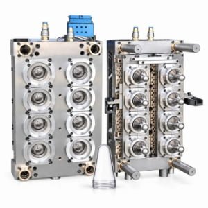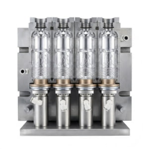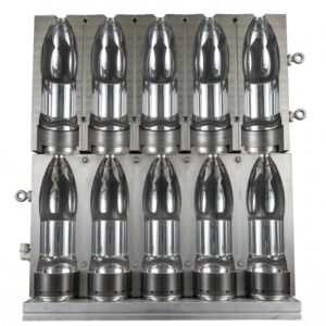
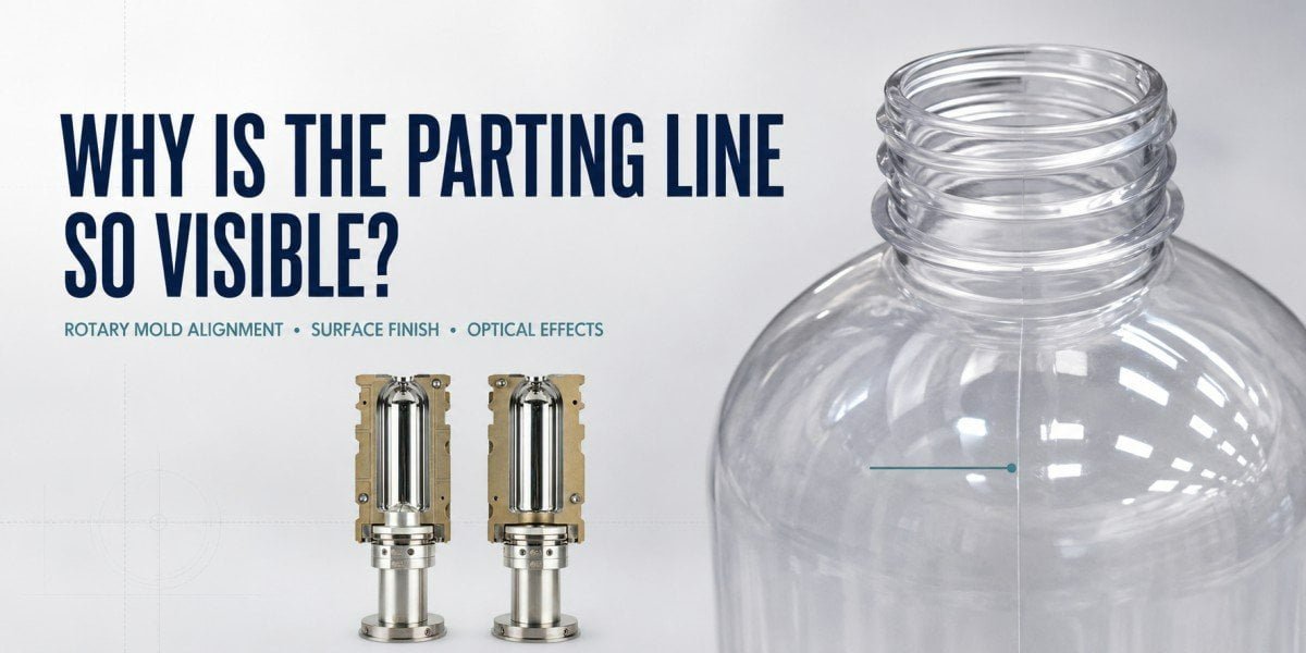
A clear round PET bottle can show a very strong vertical parting line in a photograph even when the actual geometric change at that location is extremely small. The reason may be optical reflection, surface-finish variation, a real step between two mold halves, or a combination of these factors.
A visible clear PET bottle parting line does not automatically mean the rotary blow mold is misaligned. The correct diagnosis is to determine whether the line is mainly optical, surface-related, or a real geometric mismatch before deciding how the mold should be corrected.
This distinction is especially important for transparent, smooth, unlabeled bottles. Their appearance can magnify very small differences that would be much less noticeable on an embossed, textured, colored, or fully labeled container.
From our manufacturing experience, we do not decide to polish or modify a rotary blow mold simply because a customer sends us a photograph showing a strong line. We first want to know whether the line can actually be felt, whether its visual strength changes with lighting, and whether bottles from different blow stations show the same condition.
Visible does not always mean misaligned.
Is Every Visible Parting Line on a Clear PET Bottle a Mold Defect?
No. A two-half PET blow mold naturally has a parting position, so a fine forming trace can remain on the bottle without indicating a mold defect. The engineering question is whether that normal trace has become an unacceptable visual line, a measurable step, or an inconsistent feature between blow stations.
A conventional PET blow mold cavity is commonly formed by two mold halves that close around the preform before stretching and blowing occur.
Where those cavity halves meet, there is a parting location.
The PET expands against both sides of the cavity during high-pressure blowing. A very fine trace at the interface can therefore be visible on the finished bottle, especially under directional lighting.
The existence of the line itself is not enough to diagnose the mold.
What matters is the nature of the line.
| Bottle Observation | Initial Interpretation | First Diagnostic Direction |
|---|---|---|
| Fine line visible under strong light but almost impossible to feel | May be normal optical or surface-finish visibility | Change lighting and viewing angle |
| Line is visible and a clear step can be felt with a fingertip or nail | Geometric mismatch becomes more likely | Check mold-half alignment and station condition |
| Line is much stronger only in one local region | Local mold geometry or surface condition may be involved | Inspect the corresponding parting area |
| Line looks strong in a photograph but weak under diffuse light | Optical amplification may be significant | Compare several lighting conditions |
| Only one rotary station produces the strong line | Local tooling or station positioning deserves attention | Compare that station with neighboring stations |
| All stations show a very similar line | Common mold design, machining, polishing, or optical factors become more relevant | Review the complete mold set and bottle design |
This is also why a single photograph should be treated carefully.
A clear bottle photographed against a bright background can create a high-contrast vertical reflection. The camera may make this reflection look much wider than the physical feature that created it.
If the actual parting location has only a very small change in curvature or gloss, the optical line may still extend across several pixels in the photograph.
That does not mean the PET has a mechanical step of the same apparent width.
Normal Parting Trace vs. Parting-Line Defect
For practical troubleshooting, we prefer to separate two questions.
The first is:
Is there a parting trace?
The second is:
Is that trace outside the appearance or dimensional requirement of the bottle?
A transparent cosmetic-style beverage bottle with no label may have a much stricter visual requirement than a bottle covered by a full-body sleeve.
The mold evaluation should therefore reflect the actual package.
A parting line can be technically small and still commercially unacceptable if it falls in a highly visible area of a premium transparent bottle.
Conversely, a line that appears dramatic in one close-up photograph may be difficult to notice under normal consumer viewing conditions.
Both engineering measurement and visual evaluation matter.
Why Do Clear Round PET Bottles Make Parting Lines Look More Obvious?
Transparent PET, a continuous round surface, and directional lighting can visually amplify very small changes at the mold parting position. A narrow difference in curvature or surface gloss can interrupt the bottle’s highlight and create a bright or dark vertical line that appears much larger than the actual physical feature.
This optical effect is one of the main reasons clear round bottles deserve a separate discussion from general blow mold parting-line troubleshooting.
A smooth cylindrical PET bottle behaves almost like a curved optical surface.
Light reaches the outside surface, part is reflected, part enters the transparent PET, and further reflections and refractions can occur through the bottle wall.
As the bottle curves around its circumference, the angle between the surface and the light source changes continuously.
This creates the familiar bright vertical highlight seen on many clear bottles.
If the surface continuity changes slightly at the parting line, that highlight can also change abruptly.
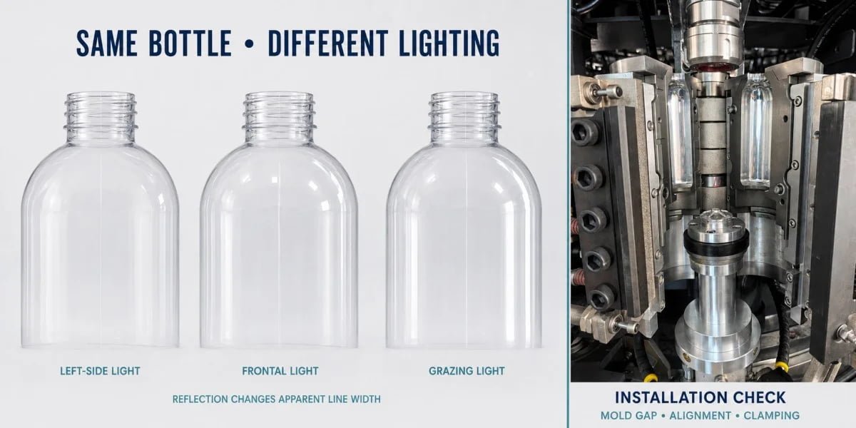
A Small Geometric Change Can Create a Large Visual Change
Consider a nearly smooth circular bottle cross-section.
If the mold halves meet with excellent geometric continuity, the reflected highlight can remain relatively smooth across the parting location.
Now introduce a very small local change in surface angle.
The physical displacement may be small, but the reflection direction can change enough that the camera receives much more or much less light from that narrow region.
The result can appear as:
- a bright vertical line;
- a dark vertical line;
- two closely spaced lines;
- a wider-looking reflective band.
This is why the apparent visual width of a seam should never be used directly as a measurement of actual mold mismatch.
Surface Gloss Can Produce a Similar Effect
The same optical amplification can occur even when the two cavity halves are geometrically well aligned.
Suppose one side of the parting area has a slightly different polishing condition from the other.
The PET formed against these two surfaces may reproduce a small difference in gloss or microtexture.
Under diffuse light, the difference may be difficult to see.
Under directional light, it can become very obvious.
| Surface/Bottle Characteristic | Effect on Visual Parting-Line Appearance |
|---|---|
| High transparency | Allows stronger reflection and refraction effects |
| Smooth polished body | Makes local gloss changes easier to see |
| Circular body profile | Creates continuous highlights that can be interrupted by a small surface change |
| Bright directional lighting | Increases contrast around subtle curvature differences |
| Dark background | Can strengthen bright reflections |
| Bright background | Can strengthen dark optical boundaries |
| Unlabeled bottle | Leaves the full vertical parting area exposed |
| Colored, textured, or embossed bottle | May visually mask a small parting trace |
This is one reason a clear cylindrical bottle can be more demanding aesthetically than a more complicated-looking bottle.
Its apparent simplicity gives small surface differences nowhere to hide.
How Can You Tell an Optical Line From a Real Mold-Half Mismatch?
Do not rely on one photograph. Rotate the bottle under different lighting, inspect the same line by touch, compare both parting sides, and then compare bottles from multiple blow stations. A line that changes strongly with light but has almost no tactile step is more likely to involve optical or surface effects.
The diagnosis can begin without immediately measuring or dismantling the mold.
The first useful tool is the bottle itself.
Change the Lighting Before Changing the Mold
Hold the bottle under a relatively diffuse light and slowly rotate it.
Then repeat the observation under a directional light source.
Watch what happens to the apparent line.
If the line becomes dramatically stronger, weaker, wider, or narrower as the bottle rotates, optical reflection is contributing significantly to what you see.
That does not prove the mold is perfect.
A small real geometry difference can create the optical effect.
But it does tell us that the photograph is amplifying the physical feature.
Feel the Parting Position
A true mold-half mismatch may create a step between the two sides of the bottle surface.
Depending on its magnitude, that step may be detectable by moving a fingertip or fingernail carefully across the parting position.
The comparison should be made at several heights.
Do not check only the center body.
Inspect the shoulder, body, lower body, and other relevant smooth regions.
A mismatch may not be identical from top to bottom.
| Field Test | What You Observe | More Likely Interpretation |
|---|---|---|
| Rotate bottle under different lights | Line intensity changes substantially | Optical effect is significant |
| Touch the line with fingertip | Almost no detectable height difference | Surface/optical cause deserves more investigation |
| Move a fingernail across the line | Repeated physical step can be detected | Real geometric mismatch becomes more likely |
| Compare line from shoulder to base | Only one area becomes much stronger | Local mold condition may be involved |
| Inspect both vertical parting positions | One side is clearly different from the other | Local geometry, surface, or alignment difference |
| Compare multiple stations | One station consistently differs | Local station/tooling investigation |
Compare the Bottle From Both Sides
A two-half mold creates two longitudinal parting regions around the bottle.
If one side of the bottle is dramatically more visible than the other, that information matters.
It can help separate a general optical characteristic of the bottle design from a local mold condition.
A perfectly symmetrical optical effect would be more likely to appear similarly at both parting locations, although actual lighting conditions can still make one side appear stronger.
Use Magnification Only After Establishing the Basic Pattern
Close-up cameras and magnification are useful, but they can also exaggerate features.
We prefer to establish the basic production pattern first:
Is it all stations?
One station?
One side?
One height?
All lighting conditions?
Only certain viewing angles?
Once that pattern is clear, magnified images become much more useful because the engineer knows what is being compared.
This diagnostic approach is similar to other PET bottle appearance problems: the first task is to separate the symptom from the actual source. Our article Preventing PET Bottle Scratches: Is Your Mold or Blow Molding Machine to Blame? discusses the same principle for another type of visible bottle defect.
How Does Rotary Blow Mold Alignment Affect the Parting Line?
When a rotary blow mold closes, the two cavity halves must repeatedly return to the correct relative position. If one half sits slightly higher, lower, or laterally displaced at the parting region, the finished PET bottle can reproduce that difference as a physical step. Manufacturing accuracy and repeatable positioning on the blow station both matter.
This is where the problem moves from optical appearance into mechanical engineering.
The cavity surfaces on the two halves should meet so that the final bottle contour remains continuous across the parting location.
If that continuity is interrupted, PET can reproduce the discontinuity.
The result may be a detectable step at the parting line.
Mold Machining Accuracy Is Only One Part of Alignment
When buyers hear “mold alignment,” they sometimes assume the only possible cause is CNC machining.
That is too narrow.
A rotary blow mold is manufactured as tooling and then installed into a machine station.
The final production position therefore depends on several layers.
| Alignment Layer | Why It Matters |
|---|---|
| Cavity machining | Determines the geometry of each mold half |
| Mold-half matching | Determines whether the two cavity contours correspond correctly |
| Locating features | Help the mold return to the intended closed position |
| Mounting surfaces | Transfer mold position into the machine |
| Installation condition | Incorrect seating can affect the final relationship |
| Blow-station mechanism | Must close and position the mold repeatedly |
| Wear or contamination | Can influence how parts seat over long production periods |
| Repeatability | A good static position is not enough if it changes cycle to cycle |
This is particularly important on rotary machines because the same bottle design is produced simultaneously across multiple stations.
Those stations create an immediate comparison group.
Why Station-to-Station Comparison Is So Powerful
Suppose a rotary blow molder has 12 blow stations.
All 12 receive the same preform type.
They operate under the same general heating recipe.
They produce the same bottle design.
If the bottles from 11 stations show only a fine parting trace while one station consistently produces a tactile step, the investigation becomes much narrower.
The bottle design itself is less likely to be the main explanation.
Attention should move toward:
- that particular mold set;
- how it is installed;
- its two mold halves;
- its locating condition;
- the mechanical positioning of that blow station.
Now reverse the situation.
If all 12 stations show a similar highly visible but barely tactile line, a common surface, design, polishing, or optical issue becomes more plausible.
This is why rotary mold troubleshooting should use the machine architecture rather than examining one random bottle in isolation.
For buyers working with this equipment category, our High-Speed Rotary Blow Molds for Krones & Sidel guide explains why rotary tooling has to be evaluated as a machine-specific system rather than only as a bottle cavity.
Why Can Surface Finish Make a Parting Line Visible Even Without a Large Step?
Parting-line appearance depends on both geometric continuity and surface continuity. Two mold halves can be mechanically well aligned while a difference in polishing, machining texture, or local edge treatment causes the transparent PET surface to reflect light differently on either side of the parting location.
This is one of the most easily misunderstood situations.
A customer sees a bright vertical line and asks:
“Are the two molds offset?”
The answer may be no.
The cavity geometry may be aligned closely, but the surfaces beside the parting location may not have exactly the same optical finish.
For clear PET, that difference can be transferred to the bottle.
Why Clear Smooth Bottles Are Sensitive to Finish Differences
A textured bottle already contains many intentional surface changes.
Light is scattered across those details.
A transparent smooth bottle behaves differently.
A large polished panel reflects light in a much more continuous way.
If that continuity changes at one vertical location, the human eye notices it quickly.
This is similar to seeing a small polishing transition on a glossy automotive panel: the physical depth may be extremely small, but the reflected light makes it obvious.
Surface Continuity Is More Than “How Shiny Is the Mold?”
Surface finish near the parting region can be influenced by several factors.
The relevant issue is not simply whether the cavity looks polished.
The two sides need to produce sufficiently similar PET appearance after blowing.
| Mold Surface Condition | Possible Bottle Appearance |
|---|---|
| Similar polishing on both sides | More continuous visual reflection |
| Different polishing direction | Vertical line may become more visible under directional light |
| Local machining marks near one half | Gloss can differ at the corresponding bottle area |
| Overworked parting edge | Local geometry or surface transition may change |
| Small scratch near parting region | May create an additional reflected line |
| Uneven local repair | Can create a visual boundary even if gross alignment is acceptable |
This is why parting-line appearance is controlled by both geometry and surface continuity.
More Polishing Is Not Automatically Better
If one side has a surface-finish problem, careful correction may improve the bottle appearance.
However, unnecessary polishing close to the parting edge can create new problems.
If material is removed unevenly, a previously good geometric edge may change.
The repair technician can accidentally convert a surface-finish problem into a geometry problem.
For this reason, polishing should follow diagnosis.
It should not be the automatic response to every visible line.
Our PET Blow Mold Preventive Maintenance guide discusses why cavity surfaces, locating areas, and mold condition should be maintained carefully rather than repaired aggressively only after visible problems develop.
Why Can One Rotary Blow Mold Station Produce a Stronger Line Than the Others?
If one rotary blow station repeatedly produces a stronger or more tactile parting line while other stations produce acceptable bottles, the investigation should focus first on that station and its mold set. If all stations produce a similar line, common bottle, mold-design, machining, polishing, or optical factors become more relevant.
This is one of the biggest diagnostic advantages available to a rotary PET bottle producer.
Do not waste that information.
Each station is effectively producing another sample under closely related process conditions.
Separate Common Problems From Local Problems
The pattern across stations can quickly divide the possible causes.
| Production Pattern | More Useful Investigation Direction |
|---|---|
| Only one station has a strong line | Inspect that mold set, installation, locating condition, and station |
| Two or three stations are worse than the others | Compare those mold sets and corresponding machine positions |
| Every station shows a similar visible line | Review common cavity design, surface finish, polishing standard, and optical behavior |
| One station changes from good to bad during production | Investigate repeatability, seating, wear, contamination, or machine condition |
| Line appears at exactly the same height on every bottle | Common geometry or surface feature becomes more relevant |
| Different stations show different local problems | Manufacturing, assembly, maintenance, or station-specific factors need comparison |
Real Case: Stations 3 and 6 Produced Stronger Parting Lines on a 1 L PET Bottle
We encountered this exact diagnostic situation during a 1 L PET bottle project customized for Hema supermarket in China.
The bottle was a larger 1 L format that has become increasingly popular in the Chinese retail market. During production, the customer’s workshop team contacted us because they found that the parting lines on a batch of bottles looked noticeably wider and more obvious than expected.
The bottles were being produced on a Chinese Tech-Long rotary blow molding machine.
At this point, we did not immediately conclude that the cavity machining or polishing was incorrect.
The first question I asked the production team was:
“Does this happen randomly, or does it come mainly from specific blow stations?”
The customer checked the production samples and told us that stations No. 3 and No. 6 produced the problem more frequently.
That information immediately changed the troubleshooting direction.
If the bottle design itself or the complete mold set had the same common problem, we would expect the symptom to appear much more consistently across all stations.
Because stations 3 and 6 were showing the problem more often, we focused first on those two mold positions and their installation condition.
The Second Question: Is the Strong Parting Line on One Side or Both Sides?
The next question I asked was equally important:
“Is only one parting line wider, or are both sides of the bottle affected?”
The workshop team confirmed that both longitudinal parting lines were noticeably wider.
This distinction gave us another useful clue.
If only one local section of one parting line had been abnormal, we would have paid more attention to a localized cavity edge, surface condition, or mold-half matching issue.
In this case, however, both parting sides were affected on the same bottles.
That made the overall installation and closing relationship of the mold more important to inspect.
| Troubleshooting Question | Customer Feedback | What It Told Us |
|---|---|---|
| Did every blow station produce the same problem? | No | The issue was unlikely to be only a common bottle-design factor |
| Which stations showed the problem most often? | No. 3 and No. 6 | Inspection could focus on specific mold positions |
| Was only one parting side affected? | No | The problem was not limited to one isolated parting edge |
| Were both bottle parting lines noticeably wider? | Yes | Overall mold installation and closing condition needed closer inspection |
| Was a fixed manufacturing defect immediately assumed? | No | Installation and station conditions were checked before modifying the mold |
What We Eventually Found
After checking the corresponding stations and mold installation, we found that there was an installation gap when the molds had been mounted.
Because the mold was not seated in the intended installation condition, the two halves were not achieving the expected closing relationship during production.
This made the bottle parting lines appear wider.
After the mounting condition was corrected and the installation gap was eliminated, the parting-line problem was resolved.
The important point from this case is that the mold itself did not need to be immediately polished or remachined.
The correct diagnosis came from asking two very simple production questions first:
- Which blow stations are producing the abnormal bottles?
- Is the abnormal parting line on one side or on both sides of the bottle?
Those two answers reduced the troubleshooting range significantly.
Why Did “Both Sides” Matter in This Case?
A rotary PET bottle normally has two longitudinal parting locations created by the two mold halves.
When both sides become abnormal on bottles from the same station, we should not automatically treat the problem as one damaged local edge.
The complete closing and positioning condition of that mold set deserves attention.
In our Hema 1 L bottle project, that is exactly where the investigation led.
The problem was associated with the mold installation gap at the affected rotary positions, rather than something that could have been solved simply by polishing the visible line.
What Would Have Happened If We Had Polished the Mold First?
This case also explains why we do not recommend choosing the repair method from a bottle photograph alone.
If we had assumed:
“The parting line looks wide, so the cavity needs more polishing,”
we could have modified a mold surface that was not the root cause.
The installation gap would still have remained.
The bottle could still have shown the same basic problem, while unnecessary polishing around the parting edge could have introduced another geometric variable.
Instead, the production pattern gave us the correct direction.
Specific stations + both parting sides affected → inspect the complete mold installation and closing condition before modifying the cavity surface.
Our Engineering View
From our manufacturing and troubleshooting experience, a visible parting line on a rotary PET bottle should be treated as a production pattern, not just as a photograph.
For this Hema 1 L project, the most useful information was not simply that “the line was too thick.”
The useful information was that stations No. 3 and No. 6 produced the condition more frequently, and both sides of the bottle showed the stronger parting line.
That allowed us to move from a general appearance complaint to a specific mechanical inspection.
After the mold-installation gap was corrected, the issue was resolved.
This is why, when an overseas or domestic rotary blow mold customer contacts us about a visible parting line, one of our first requests is to separate samples by blow station.
For rotary blow molds, station information can often tell us more than one highly magnified bottle photo.
Mark Samples by Station
This sounds simple, but it is often missed.
If bottles are mixed together immediately after production, much of the diagnostic value is lost.
When investigating a rotary mold problem, collect and label samples by blow station.
For example:
Station 1
Station 2
Station 3
Station 4
Then compare the same parting location under the same light.
Do not compare one bottle photographed today with another photographed tomorrow under a different lamp.
Controlled comparison makes subtle differences much easier to interpret.
What If the Same Station Is Sometimes Good and Sometimes Bad?
That pattern is important.
If a mold had a fixed machined mismatch, we would generally expect the geometric symptom to be repeatable.
If the same station alternates noticeably between acceptable and unacceptable bottles, the investigation should also include dynamic positioning and repeatability.
Possible areas to evaluate include:
- whether the mold closes consistently;
- whether a locating area contains contamination;
- whether wear affects repeat positioning;
- whether the station has mechanical play;
- whether the mold is seated correctly.
The exact cause must be confirmed from the actual machine.
The point is that a variable symptom suggests a different diagnostic direction from a permanent machined step.
The principle of comparing cavity or station consistency also appears in our 30ml Capacity Variance in Same-Batch PET Blow Molds: A CNC Manufacturing Analysis. That article discusses a different defect, but the same engineering idea applies: variation between cavities or stations is valuable evidence about where the problem originates.
When Can Polishing Help—and When Will Polishing Not Solve the Problem?
Polishing can improve a parting-line appearance when the main cause is a local surface-finish difference, but it cannot correctly reposition two geometrically misaligned mold halves. The repair method should be selected only after determining whether the line comes from optics, surface continuity, geometry, or machine positioning.
Customers often ask a reasonable question when they see a visible vertical line:
“Can you polish the mold again?”
Sometimes the answer is yes.
Sometimes polishing is the wrong repair.
When Polishing May Help
If inspection shows that:
- there is almost no detectable physical step;
- the geometric relationship of the two mold halves is acceptable;
- the line is associated with a clear difference in gloss or local surface texture;
- the problem remains concentrated around a surface-finish transition;
then controlled surface correction may be appropriate.
The key word is controlled.
The technician should preserve the cavity geometry and the parting edge while improving surface continuity.
When Polishing Will Not Correct the Root Cause
If a real step exists because the mold halves are offset, removing surface material does not relocate the cavity halves.
Likewise, if the problem comes from how the mold is seated in the station, polishing the cavity does not correct the installation.
If the station is not repeating consistently, polishing does not repair machine repeatability.
| Confirmed Condition | More Appropriate Direction | Why |
|---|---|---|
| Optical line with no meaningful surface or geometry defect | No immediate mold correction; evaluate appearance under agreed viewing conditions | Physical modification may not be justified |
| Surface gloss/finish difference | Controlled surface correction may help | Cause is primarily surface continuity |
| Real mold-half step | Evaluate geometric alignment and mold-half matching | Polishing does not reposition the halves |
| Mold installed incorrectly | Correct installation and seating | Cavity modification may create a new problem |
| Station repeatability issue | Inspect machine/station positioning | Mold polishing cannot stabilize the station |
| Local damage at the parting area | Evaluate repair according to damage | Repair must address the actual affected geometry/surface |
| All stations show the same optical line | Review common design/finish and bottle appearance requirements | A single-station repair will not solve a common condition |
Why Aggressive Polishing Can Make Things Worse
The parting area is geometrically sensitive.
The cavity contour on one mold half must continue correctly into the contour on the opposite half.
If polishing rounds or removes material from one edge more than the other, the surface can lose continuity.
A repair intended to remove a bright line can then create a physical deviation.
This is why our approach is:
Do not choose the repair method from the appearance of the line alone. Diagnose the cause first.
Our Engineering View
When we receive a clear-bottle photo with a very strong-looking parting line, we do not start by promising another polishing operation.
We first ask for comparison information.
Can the line be felt?
Does it change with light?
Is it the same on both sides?
Which station made the bottle?
Do other stations show the same line?
Is the symptom consistent from bottle to bottle?
Those questions usually tell us more than repeatedly enlarging the same photograph.
Only after the pattern is understood do we decide whether the next inspection belongs on the bottle surface, the mold surface, the mold alignment, or the rotary station.
What Should Be Checked Before Correcting a Visible Parting Line on a Rotary Blow Mold?
Before modifying the mold, collect bottles by station, compare them under consistent lighting, check whether the line is tactile, and document where the symptom changes along the bottle height. This allows the mold supplier to distinguish common optical appearance from a local mold or station issue before tooling is unnecessarily polished or remachined.
The fastest repair is often the repair that begins with good evidence.
For an overseas rotary blow mold customer, this matters even more because an incorrect diagnosis can lead to unnecessary mold disassembly, shipment, or modification.
Step 1: Collect Station-Specific Bottles
Do not send us five random bottles from one production bin.
If possible, collect bottles from identifiable stations.
Use the same preform batch and stable production conditions.
Mark each sample.
Step 2: Photograph Under Controlled Lighting
Use the same background and approximately the same bottle orientation.
Then deliberately change the light angle for a second set of photos.
This makes optical behavior much easier to see.
A useful photo set can include:
- diffuse front light;
- directional side light;
- dark background;
- bright background.
The objective is not photography quality.
It is to determine whether the apparent line behaves like a reflection or like a fixed geometric feature.
Step 3: Provide a Slow Rotation Video
A short close-range video is often more useful than a single still image.
Slowly rotate the bottle while keeping the camera approximately fixed.
If the line becomes stronger and weaker as the reflection passes around the bottle, that is valuable optical evidence.
Step 4: Check the Physical Step
If the customer can feel a clear step, say so.
If the customer cannot feel anything but the photograph looks dramatic, say that too.
Do not force a conclusion simply because the line looks large on screen.
Step 5: Compare Stations Before Removing the Mold
For rotary blow molds, this is often the highest-value diagnostic step.
| Information to Send the Mold Supplier | Why It Helps |
|---|---|
| Bottle samples identified by station | Separates local and common problems |
| Close-up photos under the same lighting | Allows direct visual comparison |
| Video while rotating the bottle | Shows whether reflection changes the line appearance |
| Confirmation whether the line can be felt | Helps distinguish optical/surface and geometric conditions |
| Photos of both bottle parting sides | Shows whether the condition is symmetrical |
| Station number producing the worst bottle | Directs the tooling inspection |
| Photos of the installed mold if one station is abnormal | Helps review mounting and seating |
| Photos of the corresponding cavity parting area | Helps identify local surface or edge differences |
| Description of whether the problem is constant or intermittent | Helps distinguish fixed geometry from repeatability issues |
Step 6: Inspect the Mold Only After the Pattern Is Clear
If one station is confirmed abnormal, then remove or inspect the corresponding mold as required.
Check the matching cavity areas rather than polishing the complete mold indiscriminately.
If the symptom is a physical step, the inspection should focus on alignment and geometric matching.
If the symptom is visual but not tactile, surface continuity deserves more attention.
If every station is similar, it makes less sense to immediately blame one station’s mechanical positioning.
The investigation should move toward common tooling and bottle-appearance factors.
Real Case Documentation We Recommend
For future rotary projects, we recommend keeping a simple before-and-after record whenever a strong parting-line issue is corrected.
The most useful documentation is not just two photographs labeled “before” and “after.”
It should include:
| Case Information | Why It Is Valuable |
|---|---|
| Blow molding machine/platform | Defines the rotary tooling environment |
| Total number of stations | Provides the comparison context |
| Abnormal station number | Shows whether the issue was localized |
| Whether the line could be felt | Distinguishes geometry from optical appearance |
| Original suspected cause | Records the troubleshooting path |
| Confirmed cause | Prevents the case from becoming anecdotal |
| Corrective action | Shows why the selected repair was appropriate |
| Same-angle before/after bottle photos | Makes the result comparable |
| Mold parting-area photo | Connects bottle appearance to tooling condition |
We do not recommend inventing this information simply to make a case study look complete.
A useful engineering case should show what was actually observed, how the cause was isolated, and what correction solved it.
That is the type of information we will continue adding to PETMOLDER technical articles as more documented projects become available.
For buyers sourcing replacement rotary tooling, mechanical compatibility remains part of this diagnosis as well. A mold must not only be machined correctly; it must also locate and operate correctly on the customer’s actual machine. Our article Custom Blow Molds: 4 Reasons Your New Mold Won’t Fit Your Blowing Machine explains why actual machine conditions should be verified before tooling decisions are made.
For rotary blow molds, the fastest way to diagnose a visible parting line is often not to inspect one bottle—but to compare bottles from different blow stations.
Frequently Asked Questions
Is a Parting Line Normal on a PET Bottle?
A fine parting trace can be normal on a PET bottle formed in a two-half blow mold.
The important question is whether the line is only a minor visual trace or has become an unacceptable appearance feature, a tactile geometric step, or an inconsistent condition between different blow stations.
Clear smooth bottles can make an otherwise small trace much more visible.
Why Does the Parting Line Look Stronger on a Clear Round PET Bottle?
Transparent round PET surfaces produce strong reflections and refractions.
A very small difference in curvature or gloss at the mold parting location can interrupt the continuous bottle highlight and create a bright or dark vertical line.
For this reason, the apparent width of the line in a photograph may be much greater than the actual geometric difference.
How Can I Tell Whether the Two Blow Mold Halves Are Misaligned?
Do not rely only on visual appearance.
Check whether a physical step can be felt across the line, inspect the same position at several bottle heights, and compare bottles produced by different rotary stations.
If one station repeatedly produces a tactile step while neighboring stations do not, that mold set or station should receive closer alignment inspection.
Can Polishing Remove a Visible PET Bottle Parting Line?
It can help when the main cause is a surface-finish or gloss difference near the parting region.
It will not correctly solve a real geometric mismatch between mold halves or an unstable blow-station positioning problem.
Excessive polishing near the parting edge can also alter cavity geometry, so the cause should be diagnosed first.
Why Does Only One Blow Station Produce Bottles With a Visible Parting Line?
If other stations producing the same bottle are normal, the problem is more likely to be localized.
The corresponding mold set, installation condition, mold-half matching, locating surfaces, and blow-station repeatability should be checked.
If all stations show the same line, common mold design, polishing, surface finish, or bottle optical behavior deserves more attention.
Related PETMOLDER Articles
- High-Speed Rotary Blow Molds for Krones & Sidel: A Guide to Premium Compatible Tooling
- PET Blow Mold Preventive Maintenance: A Complete Guide for Aluminum and Stainless Steel Tooling
- Preventing PET Bottle Scratches: Is Your Mold or Blow Molding Machine to Blame?
- 30ml Capacity Variance in Same-Batch PET Blow Molds: A CNC Manufacturing Analysis
- Custom Blow Molds: 4 Reasons Your New Mold Won’t Fit Your Blowing Machine