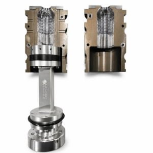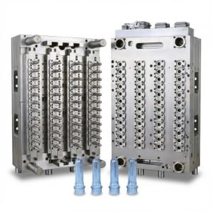
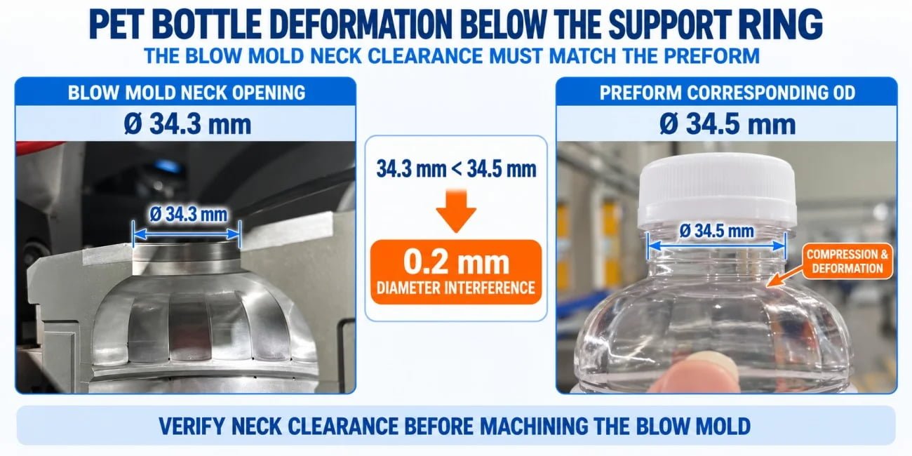
A PET bottle that repeatedly deforms directly below the support ring does not always have a heating or preform-quality problem. PET bottle deformation below the support ring can be caused by insufficient blow mold neck clearance, where the mold physically interferes with the preform before normal stretch blowing occurs. This dimensional relationship should be checked before repeatedly changing process parameters.
This was exactly what we found while helping a customer in New Zealand.
The customer had already inspected the preforms, checked the blow molds, and reviewed the heating process. Nothing appeared obviously defective when each item was examined separately. However, the same small deformation continued to appear immediately below the support ring.
The final measurements explained the problem:
| Measurement | Actual Value |
|---|---|
| Preform OD at the affected position | 34.5 mm |
| Closed blow mold neck opening | 34.3 mm |
| Diametrical relationship | 0.2 mm interference |
The preform itself was not obviously defective, and the blow mold did not show obvious surface damage. The problem existed in the dimensional relationship between the two components.
That distinction matters in PET stretch blow molding.
When a defect always appears at an interface, measure the interface before changing the process.
New Zealand Case: Why the Bottle Kept Deforming Just Below the Support Ring
The New Zealand customer's bottle deformation was caused by mechanical interference between the preform and the blow mold neck opening. The critical evidence was a 34.5 mm preform OD entering a mold region that measured only 34.3 mm when closed.
A customer in New Zealand contacted PETMOLDER for technical assistance with a rotary PET stretch blow molding application. During production, the finished bottles repeatedly showed a small localized deformation immediately below the support ring.
This was not a general shoulder distortion or an unstable bottle-body defect. The location remained remarkably consistent, which was one of the most useful clues in the diagnosis.
Before contacting us, the customer had already investigated several of the usual causes. The preforms did not show an obvious defect in the affected area, the blow mold cavity surfaces did not appear damaged, and the heating process had been reviewed without finding an abnormal condition that could convincingly explain why the deformation remained in such a narrow and fixed position. The original mold supplier had also been consulted, but the root cause was still unclear.
The customer later found PETMOLDER through a Google search and sent us information about the bottle, preform, mold, and production condition.
From our manufacturing experience, the fixed position of the defect deserved more attention than another round of heating adjustment. When a deformation consistently follows a defined mechanical interface, we do not only ask how the PET was heated or blown. We also ask what physically surrounds that part of the preform when the mold closes.
We therefore asked the customer to compare two dimensions: the actual outside diameter of the preform immediately below the support ring and the corresponding opening in the closed blow mold.
The customer measured 34.5 mm on the preform and 34.3 mm on the mold.
The cause immediately became much clearer. At that axial position, the mold did not provide free clearance around the preform. Instead, the tooling was closing around a preform region that was already larger than the available opening.
The customer subsequently reworked the corresponding neck area of the blow mold to establish an appropriate clearance. After another production trial, the deformation below the support ring disappeared.
The preforms did not need to be replaced, the complete blow mold did not need to be remanufactured, and further repeated changes to the heating recipe were not required to eliminate the defect.
The most important lesson from the case is therefore not simply the two measured numbers. It is the relationship between them:
Sometimes the preform is acceptable by itself and the blow mold has no obvious machining damage, but the two components still cannot work correctly together because their interface dimensions are incompatible.
This is particularly relevant when purchasing third-party rotary tooling. Our guide to high-speed rotary blow molds for Krones and Sidel machines explains why machine and tooling compatibility need to be evaluated as a complete system rather than by cavity shape alone.
What Is the Area Directly Below the PET Preform Support Ring?
The area directly below the support ring forms the transition between the finished neck region and the preform body that will be stretched into the bottle. Its geometry matters because this region must coexist correctly with the blow mold neck structure when the mold closes.
In conventional two-stage PET stretch blow molding, the neck finish, threads, support ring, and related neck geometry are already produced during preform injection molding. During the second-stage blowing process, the preform body is reheated and transformed into the bottle, while the neck finish is generally retained rather than stretched into the bottle body.
For an overview of this process, see our explanation of PET two-stage molding and preform reheating.
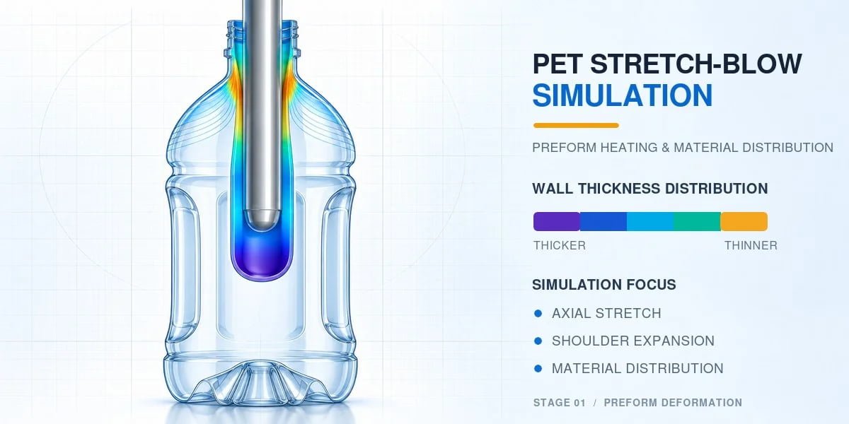
The support ring has practical functions in preform handling, supporting, conveying, or positioning, depending on the machine design. Immediately below it, however, the geometry begins transitioning toward the preform body that enters the blowing area.
This is why the mold designer cannot simply check whether the nominal neck finish "fits."
A preform can use a familiar neck finish while still having an outside profile below the support ring that differs from another preform using the same general neck designation.
In other words, a designation such as 28 mm, PCO 1881, or 30/25 does not automatically describe every external dimension below the support ring.
When we evaluate a preform for a blow mold project, we therefore look at the complete preform-to-blow-mold interface, not only the closure-related neck dimensions.
Our article about PCO 1881 preforms and blow mold compatibility provides additional background on why a neck standard should not be treated as a complete description of the preform geometry.
Why Can a 34.3 mm Mold Opening Deform a 34.5 mm Preform?
A 34.3 mm closed mold opening cannot provide free diametrical clearance for a 34.5 mm preform at the same axial position. The nominal result is 0.2 mm of diametrical interference, which can mechanically squeeze or displace the PET as the mold closes.
The basic dimensional relationship is straightforward:
34.5 mm preform OD − 34.3 mm mold opening = 0.2 mm diametrical interference.
If both components were perfectly circular and perfectly concentric, this could be simplified geometrically as approximately 0.1 mm of radial interference per side.
Actual PET production is less idealized.
The real relationship can also be influenced by preform dimensional tolerance, roundness, concentricity, mold machining tolerance, mold-half alignment, installed tooling position, and machine-side alignment. For this reason, the apparent smallness of 0.2 mm should not lead an engineer to dismiss the mismatch.
The important issue is not whether 0.2 mm looks large on a drawing. The important issue is that the available clearance has become negative.
The Interference Happens Before Normal Bottle Expansion
In a correctly matched system, the preform should be positioned relative to the blow mold without unintended mechanical compression in this region. The heated preform body can then undergo stretching, pre-blow, and high-pressure blowing according to the intended process.
In the New Zealand case, the relevant preform region was already larger than the opening surrounding it.
That changes the sequence.
Instead of beginning from a freely positioned condition, the PET was mechanically constrained as the tooling closed. This is fundamentally different from a defect caused primarily by an incorrect heating profile or blowing-pressure setting.
It also explains why repeated adjustments to the blowing recipe would have difficulty eliminating the root cause.
Why the Defect Appeared in a Fixed Position
The interference was defined by geometry, so the symptom followed that geometry.
The same part of the preform repeatedly entered the same restrictive part of the mold. As a result, the deformation stayed close to the same axial region below the support ring.
This repeatability is diagnostically useful.
A defect that moves or changes dramatically with process conditions often directs attention toward thermal or blowing stability. A defect that remains tightly linked to one geometric interface should encourage the engineer to inspect that interface physically.
That does not mean every fixed defect is caused by neck clearance. It means defect location should influence troubleshooting priority.
How Can You Tell Neck Clearance Interference From a Heating or Preform Problem?
A deformation tightly concentrated below the support ring, particularly when the rest of the bottle forms normally, is a strong reason to compare the preform OD with the corresponding blow mold opening. Heating should still be evaluated, but the fixed defect location may point more directly toward a mechanical interface issue.
PET bottle deformation can have many causes. We discuss the broader subject in our PET bottle deformation troubleshooting guide.
The mistake is not checking the heating process. The mistake is assuming that heating must be responsible for every deformation simply because the bottle is produced by stretch blow molding.
A more useful approach is to interpret the defect together with its location, repetition pattern, cavity distribution, and the condition of the unblown preform.
| Production Observation | More Relevant Area to Investigate |
|---|---|
| Deformation repeatedly appears directly below the support ring | Preform OD and blow mold neck clearance |
| A local mark remains at a fixed circumferential position | Mold closing, alignment, or localized mechanical contact |
| Shoulder and bottle body also form poorly | Heating profile, stretch, pre-blow, and blowing process |
| The preform is already distorted before entering the blow mold | Preform quality, handling, or unwanted heating |
| The preform looks normal before blowing but deformation appears after mold interaction | Mold and machine interface |
| Neck finish becomes oval or distorted | Neck heating, handling, machine interface, and neck protection |
| The defect disappears after correcting the neck opening | Strong evidence supporting a clearance-related root cause |
Heating-related defects often appear together with additional evidence in wall thickness distribution, shoulder development, stretching behavior, base formation, or material appearance. By comparison, a narrow deformation attached to one fixed interface may justify mechanical measurement much earlier in the troubleshooting sequence.
This is why we use the simple principle:
Defect location is evidence.
The bottle records both the thermal and mechanical conditions experienced during production. Engineers should use that information rather than assuming that every visible defect was created by blowing pressure.
Which Preform and Blow Mold Dimensions Should Be Compared Before Machining the Mold?
A rotary blow mold should be designed around the exact preform geometry, not only around the commercial name of the neck finish. The supplier should evaluate the preform drawing together with actual samples whenever possible, especially around the support ring and the transition immediately below it.
Buyers often begin a mold inquiry with a neck description such as "28 mm," "PCO 1881," or "30/25." These descriptions are useful because they establish important information about the neck and closure system, but they do not fully define the shape of the preform below the support ring.
When we evaluate a bottle drawing and preform combination, the relevant question is not simply whether the closure fits the neck. We also need to understand whether the physical preform can enter, sit inside, and operate correctly with the intended mold and machine.
The critical information around this area typically includes the neck finish configuration, support ring geometry, support ring diameter and axial position, the preform outside profile immediately below the ring, transition radii or tapers, and the nearby preform body diameter. Preform length and concentricity may also become relevant depending on the machine and mold structure.
For buyers, the practical distinction is important:
The preform drawing tells us what should fit. The physical preform confirms what will actually enter the machine.
This is why we prefer to review both documentation and real samples on projects where dimensional compatibility is sensitive.
A drawing may be outdated, the factory may have changed preform suppliers, or several commercially "equivalent" preforms may actually have different body profiles. Physical samples help verify whether the drawing being used for mold design represents current production.
The same logic applies to dimensional concentricity. Even if the nominal diameter appears compatible, eccentricity can reduce the actual radial clearance on one side. Our article on PET preform concentricity and mold precision explains why nominal dimensions alone do not always describe the full production condition.
How Should Blow Mold Neck Clearance Be Measured and Specified?
Blow mold neck clearance should be established from the actual preform envelope, dimensional tolerance, mold tolerance, and alignment condition. There is no universal clearance value that can be applied safely to every PET preform and every blowing machine.
It would be convenient to give buyers a simple rule such as "always make the opening 0.3 mm larger." From a mold-design perspective, however, that would be misleading.
Different preforms, neck structures, machine platforms, mold designs, and alignment conditions create different requirements. The correct objective is therefore not to follow one fixed clearance number, but to confirm that the system retains suitable clearance across the actual production tolerance range.
A practical measurement process should cover the following points:
| Evaluation Stage | What Should Be Confirmed | Why It Matters |
|---|---|---|
| Measurement position | The preform and mold are measured at the same axial location | A tapered preform can have different diameters only a few millimeters apart |
| Preform samples | More than one sample is measured where practical | One preform does not represent the complete manufacturing variation |
| Preform specification | Nominal dimension, tolerance, roundness, and relevant concentricity are reviewed | Maximum production size can differ from the nominal CAD value |
| Mold opening | The corresponding opening is measured in the relevant closed condition | The production preform interacts with the assembled tooling, not an isolated CAD feature |
| Alignment | Mold halves and preform positioning are checked | Positive nominal clearance can be reduced by eccentricity or misalignment |
| Production validation | Bottles are inspected after correction, preferably with cavity identification | Confirms that the root cause has been removed without creating another problem |
The tolerance relationship is especially important.
A design should not be approved by comparing only a nominal preform diameter with a nominal mold diameter. The useful engineering question is whether adequate clearance remains after considering the expected preform size range, mold manufacturing tolerance, and actual alignment condition.
The New Zealand case was unusually obvious because the nominal measured relationship was already negative: 34.5 mm versus 34.3 mm.
In many other projects, the nominal values may appear acceptable while the worst-case production condition approaches contact.
That leads to an important principle:
Clearance must be designed—not discovered after production starts.
Why Can Both the Preform and Blow Mold Pass Inspection but Still Fail Together?
A preform and blow mold can each satisfy their individual drawings and still be incompatible as a production system. This can happen when the mold was designed using incorrect, incomplete, outdated, or different preform data.
This situation can be confusing for procurement managers because both suppliers may appear to have valid inspection reports.
The preform supplier may measure the preform and confirm that it falls within the approved preform drawing. The mold supplier may measure the tooling and confirm that the mold was manufactured according to the CAD data received for the project.
Both statements can be correct.
The unresolved question is whether the mold was designed around the exact preform that the factory is now running.
For example, the tooling may have been designed using a previous preform supplier's drawing, an old drawing revision, a commercial neck designation without the full preform body geometry, or an incomplete dimensional reference that did not clearly define the area below the support ring.
In that situation:
Part A can be correct. Part B can also be correct. Yet A + B can still be incompatible.
This is why compatibility cannot always be verified by inspecting individual components in isolation.
From our manufacturing perspective:
Compatibility is a system property.
The same principle applies beyond the preform itself. A third-party rotary mold also has to match the blowing machine in areas such as mounting geometry, cavity pitch, mold height, base mold arrangement, cooling connection, and other machine-specific interfaces.
Our article about why a custom blow mold may not fit the blowing machine explains this broader compatibility issue in more detail.
Should the Blow Mold Neck Opening Simply Be Made as Large as Possible?
No. Insufficient clearance should be corrected, but enlarging the neck area without an engineering reference is not a good design method. The opening must provide sufficient clearance while remaining compatible with the preform transition, bottle geometry, mold structure, and machine.
Once a customer discovers that a small opening can squeeze the preform, the immediate reaction may be to make the opening significantly larger.
That solves only one side of the problem.
The neck region is still part of an engineered mold system. Its geometry establishes the transition between the retained neck area and the bottle region being formed. Depending on the application, it may also interact with positioning, surrounding tooling, shoulder geometry, or other machine-specific features.
The correct correction is therefore not simply to remove as much material as possible.
The manufacturer should determine a suitable opening from the actual preform size range, dimensional tolerance, mold tolerance, alignment condition, machine configuration, and original design intent.
The New Zealand dimensions should also remain specific to that case.
The fact that a 34.5 mm preform interfered with a 34.3 mm opening does not mean that every 34.5 mm preform should use the same replacement mold dimension.
The useful principle is:
Enough engineered clearance to prevent interference, but not arbitrary clearance without a dimensional reference.
What Other Conditions Can Reduce Effective Neck Clearance?
Positive nominal CAD clearance does not necessarily guarantee sufficient operating clearance. Preform eccentricity, dimensional tolerance, mold-half mismatch, and machine alignment can all reduce the real clearance available during production.
This becomes important when the mold opening is technically larger than the preform but a contact mark or deformation still appears.
For example, a preform at the upper end of its permitted diameter range may have less clearance than the nominal design suggests. If the preform is also eccentric relative to the neck axis, the available space may become uneven around the circumference.
The same effect can occur on the tooling side. A mold-half alignment problem can shift the practical opening away from the intended centerline. In PET stretch blow molds, this type of condition is better described as a mold alignment issue, cavity alignment problem, parting line mismatch, or step at the parting line, depending on what is actually observed.
Machine-side positioning also matters. A correctly manufactured mold can still experience localized contact if the preform does not enter the opening concentrically during operation.
Temperature may influence how strongly the PET responds to that contact, especially because the region below the support ring is close to the transition between the protected neck and the heated preform body. However, thermal adjustment does not turn a confirmed negative mechanical clearance into a correct dimensional relationship.
If the components physically interfere, the dimensional issue still needs to be corrected.
A Practical Diagnostic Procedure for Deformation Below the Support Ring
The most efficient diagnosis is to document the defect location first, determine whether it follows particular cavities, inspect the unblown preform, and then compare the actual preform OD with the closed mold opening before making broad process changes.
When a customer sends us a bottle with deformation close to the support ring, we first want to understand whether the symptom is fixed geometrically or changes with the process.
The investigation normally begins by recording exactly where the deformation occurs relative to the support ring and mold parting line. On a rotary machine, it is also useful to identify whether every cavity produces the same defect or whether the problem follows one specific blowing station.
That distinction is highly informative. If all cavities produce the same deformation using the same preform, a common design relationship becomes more likely. If only one cavity produces the problem, localized machining, mold alignment, or machine-station conditions deserve more attention.
The unblown preform should then be inspected before assuming that the mold is responsible. If the preform already carries deformation, ovality, handling damage, or unwanted neck heating, those conditions need to be separated from defects created during mold closing.
Once the preform itself appears acceptable, the relevant preform OD and closed mold opening should be measured at the same axial position.
If the mold opening is smaller than the actual preform envelope, mechanical interference becomes a credible root cause immediately.
If positive clearance exists, the investigation should continue into alignment, tolerance variation, machine positioning, and then the heating and blowing process.
This sequence avoids changing several process parameters before the basic mechanical relationship has even been verified.
What Information Should Buyers Provide When Ordering a Rotary PET Blow Mold?
A rotary blow mold supplier needs enough information to evaluate the bottle, preform, mold, and machine as one system. Providing only bottle volume and neck size is generally not sufficient for reliable third-party tooling development.
For a new rotary mold project, we normally divide the required information into four groups rather than treating it as a long list of unrelated items.
| Information Group | Recommended Project Data | Why the Mold Supplier Needs It |
|---|---|---|
| Bottle and application | Final bottle drawing or physical sample, required bottle volume, filling application | Defines the cavity geometry and operating requirements of the finished package |
| Blowing machine | Machine brand and model, cavity number, cavity pitch where applicable, required output | Confirms whether the tooling can physically and operationally match the existing equipment |
| Preform | Preform drawing, physical samples, preform weight, neck finish, support ring geometry | Allows the supplier to evaluate the exact preform-to-mold relationship rather than relying only on a nominal neck description |
| Existing tooling/interface references | Existing mold drawings when available and any relevant mold or machine interface data | Helps reproduce machine-specific mounting and compatibility requirements accurately |
This way of organizing the information also makes the purpose of each item clearer.
The bottle information tells us what shape has to be produced.
The machine information tells us where and how the mold has to operate.
The preform information tells us what material geometry actually enters the mold.
The existing tooling information helps confirm the machine-side interfaces that cannot be derived from the bottle drawing alone.
This is why sending only a finished bottle is usually not enough for a replacement rotary mold. The bottle defines the final cavity shape, but it does not fully describe the preform interface or the machine mounting system.
Likewise, a statement such as "28 mm neck" is not a complete preform specification. Even a recognized neck designation should ideally be supported by the actual preform drawing and physical samples.
If several preform suppliers will be used on the same production line, this should also be communicated before the mold is finalized. The supplier can then evaluate whether the relevant dimensional envelopes are compatible with one tooling design.
How We Solved the New Zealand Customer's Support-Ring Deformation Problem
The final diagnosis was confirmed by comparing two physical dimensions. The preform measured 34.5 mm at the affected position, while the corresponding closed mold opening measured 34.3 mm. Once the customer reworked that neck region to restore suitable clearance, the deformation disappeared.
The case is useful because the customer had already investigated many of the directions that would normally be checked first.
The preform looked acceptable during ordinary inspection. The mold did not show obvious surface damage. No clear heating abnormality explained why the defect remained tightly attached to the support-ring area. Previous troubleshooting had also failed to eliminate the problem.
The breakthrough came from changing the question.
Instead of asking, "Which blowing parameter should we adjust next?" we asked:
"Does the preform physically fit the mold at the exact position where the defect occurs?"
The 34.5 mm and 34.3 mm measurements answered that question immediately.
After the relevant neck area of the mold was reworked and the interference removed, the bottle was tested again and the original deformation disappeared.
The complete mold did not need to be remade, and the customer did not need to continue adjusting the heating process in an attempt to compensate for a mechanical mismatch.
The engineering lesson is straightforward:
The problem was not a defective preform. The problem was not a visibly damaged blow mold. The problem was the dimensional relationship between them.
For buyers and engineers, the broader rule is equally useful:
When a defect always appears at an interface, measure the interface before changing the process.
Buyer Checklist: Preventing Preform-to-Blow-Mold Neck Interference
Most interface problems are easier to prevent during mold design than to diagnose after the tooling has arrived at the production plant. Before approving a rotary blow mold, buyers should confirm that the supplier has enough information to verify both preform and machine compatibility.
| Check Before Mold Approval | What Should Be Confirmed |
|---|---|
| Bottle definition | Current bottle drawing or approved physical sample is available |
| Preform definition | Correct preform drawing matches the preform that will actually be used |
| Physical sample verification | Actual production preforms are available when dimensional compatibility is critical |
| Neck and support ring | Neck finish, support ring, and transition below the ring have been reviewed |
| Tolerances | Relevant preform dimensional tolerances are understood |
| Machine compatibility | Exact blow molding machine brand and model are confirmed |
| Rotary tooling geometry | Cavity number, cavity pitch, mounting, and relevant interface dimensions are verified |
| Multiple preform suppliers | Alternative preform sources have been disclosed before final design |
| Production validation | Trial bottles can be identified and compared by cavity after mold installation |
For third-party replacement molds, this review is particularly important because the new supplier may not have access to all the original machine and mold design data unless the buyer provides it.
FAQ
Why does my PET bottle deform directly below the support ring?
Insufficient blow mold neck clearance is one possible cause, especially when the deformation remains tightly concentrated below the support ring. The actual preform OD should be compared with the corresponding closed mold opening. Heating conditions, preform quality, mold alignment, and machine positioning should still be considered, but the interface dimensions should not be overlooked.
Can a blow mold neck opening be smaller than the preform diameter?
If the corresponding preform region requires free clearance within the mold opening, a closed mold dimension smaller than the actual preform OD can create mechanical interference. The resulting contact may compress or displace the PET before normal stretch blowing occurs.
How much clearance should there be between the PET preform and blow mold neck?
There is no single clearance value suitable for every PET preform and blowing machine. The required clearance should be determined from the actual preform dimensions and tolerances, mold manufacturing tolerance, concentricity, alignment, and the specific machine and tooling structure.
Can heating adjustment fix deformation caused by insufficient neck clearance?
Heating changes may alter how the PET responds to mechanical contact, but they do not eliminate a confirmed dimensional interference. If the mold physically closes against the preform, the root dimensional relationship should be corrected rather than compensated for through repeated oven adjustments.
What information should I provide when ordering a rotary PET blow mold?
Provide enough information for the supplier to evaluate the full bottle-preform-mold-machine system. This normally includes the bottle drawing or sample, filling application, exact blowing machine information, cavity configuration, preform drawing and samples, preform weight, neck finish, support ring geometry, and available reference data from the existing mold or machine.
Conclusion
PET bottle deformation below the support ring should not automatically be treated as an oven-setting problem.
When a defect repeatedly appears in a narrow and geometrically fixed area, the physical relationship between the preform and the blow mold deserves direct inspection.
The New Zealand case demonstrated this clearly. A 34.5 mm preform OD was entering a 34.3 mm blow mold neck opening, creating mechanical interference before the normal bottle-forming process could proceed freely.
Once the relevant mold neck region was correctly reworked, the deformation disappeared.
From our manufacturing experience, this is why custom PET blow mold development should not be based only on bottle volume and a nominal neck description. The supplier needs to understand the bottle that must be produced, the exact preform entering the mold, the tooling that surrounds it, and the machine in which the complete system will operate.
A component can pass its individual inspection and still fail as part of an incompatible production system.
If you are experiencing deformation below the support ring, or if you are purchasing a replacement rotary blow mold for Krones, Sidel, KHS, or another PET blowing platform, you can send PETMOLDER your bottle drawing or sample, preform drawing and samples, neck finish, preform weight, machine model, cavity configuration, required output, and filling application. We can then evaluate the relevant preform-to-mold and mold-to-machine interfaces before recommending a tooling solution.
Related PETMOLDER Articles
- Comprehensive Troubleshooting: Why Do PET Bottles Deform After Blowing and How to Fix Them
- High-Speed Rotary Blow Molds for Krones & Sidel: A Guide to Premium Compatible Tooling
- The Ultimate Guide to Preform Neck Finishes: How to Choose the Right Standard for Your Bottle
- What is PCO 1881 Neck Finish? A Complete Guide to Preforms and Blow Molds
- Custom Blow Molds: 4 Reasons Your New Mold Won't Fit Your Blowing Machine